


Connectors, Cables, and Pin Assignments
C-6
9123-A2-GB20-10July 2000
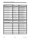
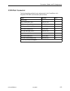
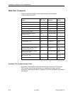
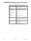
Data Port Connector
The following table provides the pin assignments for the 34-position
V.35 connector to the DTE.
Signal
ITU CT# Direction
34-Pin
Socket
Shield 101 — A
Signal Ground/Common 102 — B
Request to Send (RTS) 105 To DSU (In) C
Clear to Send (CTS) 106 From DSU (Out) D
Data Set Ready (DSR) 107 From DSU (Out) E
Receive Line Signal Detector
(RLSD or LSD)
109 From DSU (Out) F
Data Terminal Ready (DTR) 108/1, /2 To DSU (In) H
Local Loopback (LL) 141 To DSU (In) L
Transmit Data (TXD) 103 To DSU (In) P (A)
S (B)
Receive Data (RXD) 104 From DSU (Out) R (A)
T (B)
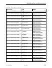
Transmit Signal Element Timing –
DTE Source (XTXC or TT)
113 To DSU (In) U (A)
W (B)
Receive Signal Element Timing –
DCE Source (RXC)
115 From DSU (Out) V (A)
X (B)
Transmit Signal Element Timing –
DCE Source (TXC)
114 From DSU (Out) Y (A)
AA (B)
Test Mode Indicator (TM) 142 From DSU (Out) NN
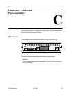
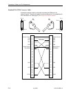
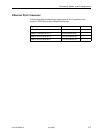
Standard V.35 Straight-through Cable
A standard V.35 straight-through cable can be used to connect a DTE port to a
DTE, where a 34-pin plug-type connector is needed for the data port and a
34-position socket-type connector is needed for the DTE. No special-order cables
are required.