


28
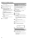
3 Select the '
t
' symbol using B or A and confirm with C .
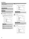
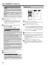
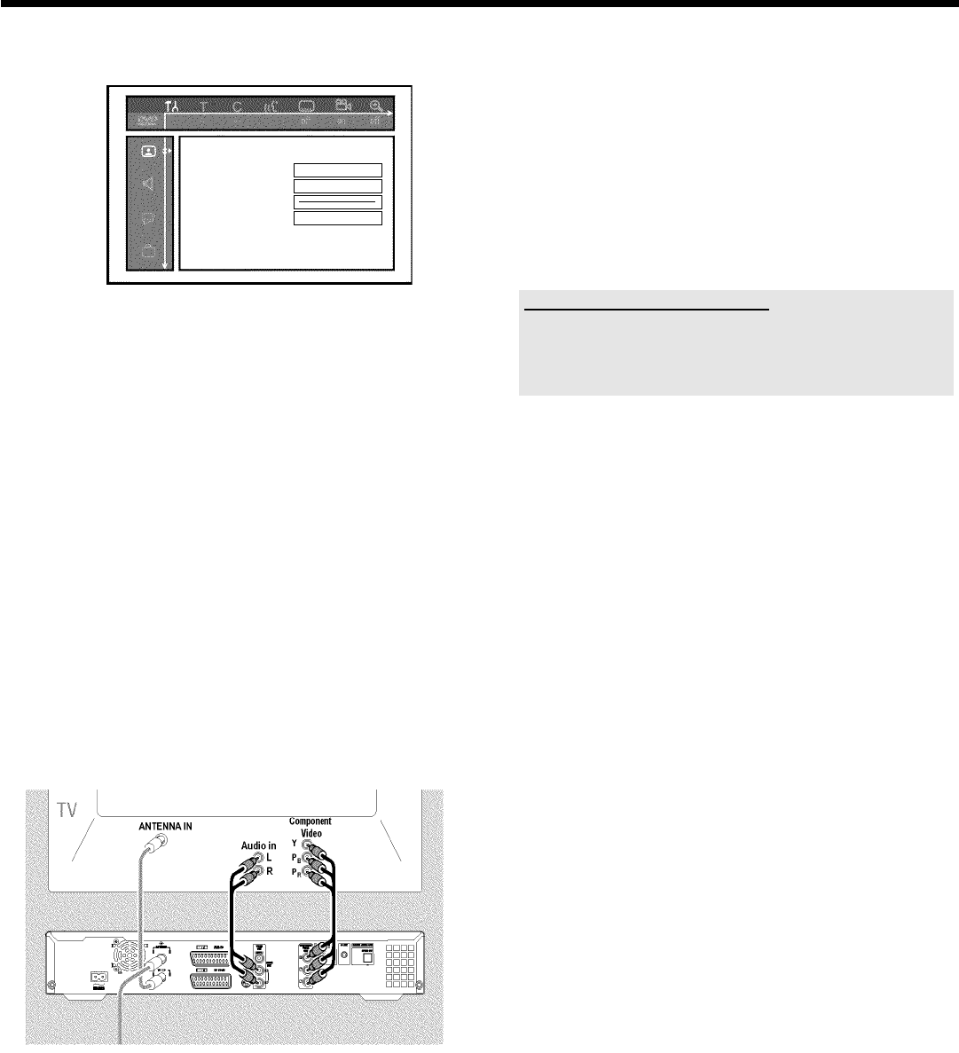
Picture
TVshape 16:9
Blacklevelshift Off
Videoshift ï
SCARTvideo RGB
4 Select the line 'SCART video' using A or B and confirm with
C .
5 Select your setting with B or A . If the YPbPr output (YUV
signal) is switched on, S-video (Y/C) and video (FBAS/CVBS) signals
will not be transmitted simultaneously.
The 'RGB' signal is switched off.
O 'S-video + YPbPr'
Component Video (YUV) and S-Video(Y/C).
GUIDE Plus+
®
menus only available on YUV ouput sockets.
O 'CVBS + YPbPr'
Component Video (YUV) and Video (FBAS/CVBS).
GUIDE Plus+
®
menus only available on YUV ouput sockets.
With all other settings, the signal is switched off at the
COMPONENT VIDEO OUT sockets. This will also be displayed
as information on the screen.
For more information on the other settings, read section 'Picture
settings' ('SCART video') in chapter 'User preferences'.
6 Confirm with OK .
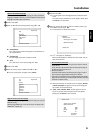
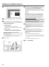
7 Use a component video (Y Pb Pr) cable, connect the three cinch
sockets (red, blue, green) COMPONENT VIDEO OUT at the
back of the DVD recorder with the corresponding three
component video (interlaced) input sockets of your TV set, usually
labelled 'Component Video Input', 'YUV Input', 'YPbPr', 'YCbCr' or
simply 'YUV'.
Warning!
Do not confuse these sockets with the five-component RGB
sockets (if available) or the yellow video (CVBS/FBAS) socket and
the two audio sockets (red/white). The five-component RGB
sockets are only provided for the R-G-B-H-V signals (red, green,
blue with horizontal and vertical synchronisation impulse).
Please observe the colour sequence
The colours of the sockets at the DVD recorder and the connectors
must match those of the socket colours at the TV set
(red-red/blue-blue/green-green). If they don't, the colours of the picture
may get mixed up or the picture may not be visible.
8 Use an audio (cinch) cable, connect the red/white cinch socket
AUDIO OUT L/R at the back of the DVD recorder with the
most coloured red/white audio input socket of your TV set
(usually labelled 'Audio in' or 'AV in'. See the instruction manual of
your TV set.)
9 If necessary, switch your TV set to the component video
(Interlaced) input sockets. If there is a switch or selection on your
TV-set between 'Interlaced' and 'Progressive scan' select
'Interlaced'. 'Progressive scan' will be not supported from this
DVD-Recorder.
Also consult the instruction manual of your TV set.
P The menu of the DVD recorder should now appear on the TV
screen. If not, check the cable connections and the settings on
your TV set.
O If necessary store this setting on your TV set.
0 End with SYSTEM MENU .
Additional installation features