


26 I-PentaMAX System Manual Version 3.A
• Camera to High Voltage supply cable: Normally supplied with the high-voltage
power supply or pulser.
• System Dependent Interface Components:
Note: An I-PentaMAX system requires a computer, which could be any one of
several different types, each requiring a different application software package. For
convenience, in discussing operating procedures, this manual refers to a PCI bus
based PC running with Princeton Instruments WinView software. Nevertheless, the
manual does apply as well to operation with other computers and software. Interface
components as follows could be required.
• PC Systems and PCI Power Mac
™
Systems: Princeton Instruments (RSPI) High
Speed Serial PCI Board: This board must be installed in the computer
(computers purchased from Princeton Instruments will be shipped with the board
already installed).
• Sun Workstations: Consult the factory.
• SGI Workstations: Consult the factory
Verifying Fuse Rating
The I-PentaMAX camera receives its power from the Temperature/Power Supply unit,
which in turn plugs into a source of AC power and can operate from a line voltage in the
range of 105-125 V or 210-250 V AC. The power requirement is 200 Watts maximum
and the line frequency can range from 47 to 63 Hz. Because the Temperature/Power
Supply unit senses the line voltage automatically, no action is required of the user if the
line-voltage selection is changed. However, the line fuse is line-voltage dependent as
indicated on the rear panel of the Temperature/Power Supply unit. Systems are ordinarily
equipped with the proper fuse for the customary line voltage for the region to which they
are being shipped.
Again, do not power up the system at any time while carrying out the instructions in this
chapter. Instructions for actual operation of the system under power are provided in
Chapter 5, First Light.
Table 1 shows the required fuse rating for each line voltage range. Only operate with a
fuse correctly rated for the intended line voltage. If the wrong fuse is installed, the
system will not be properly protected and the fuse may fail.
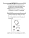
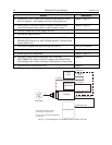
To verify that the installed fuse is correct:
1. Unplug the line cord from the power-input socket at the rear of the
Temperature/Power Supply unit.
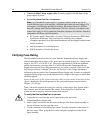
2. Insert a small screwdriver into the recess at the top of the Power Input assembly as
shown in Figure 6 and pry open the cover.
3. Use the screwdriver to loosen the fuse carrier. Note the orientation of the arrow on
the fuse carrier. Then, grasp the fuse carrier and pull it straight out of the Power
Input assembly.