


38 I-PentaMAX System Manual Version 3.A
The high voltage cable should be handled with care. Dropping the cable or banging the
connectors may damage the pins, resulting in a poor or intermittent connection.
• Connect one end of the 9-pin serial cable to the HIGH SPEED SERIAL
connector. Connect the other end to the computer interface.
Note: If the application requires use of the optional fiber-optic data link to
increase the maximum allowable distance between the Camera and the computer,
the fiber-optic “pod” would be connected to the HIGH SPEED SERIAL
connector with a short length of cable. Then the long distance fiber-optic cable
would be connected to the pod. A similar fiber-optic pod connection is required
at the computer.
• Connect a 75 Ω BNC cable from the VIDEO connector on the back of the
camera to the video monitor’s 75 Ω input. This cable must be terminated in
75 Ω. Many monitors have a switch for selecting the 75 Ω termination. A video
monitor isn’t required for viewing images, but it will provide the fastest refresh
rate.
• Connect a line cord from the Power Input assembly on the back of the
Temperature/Power Supply unit to a suitable source of AC power.
• With the HV Supply turned off, connect a line cord to the HV Supply and, if
present, the pulser.
• Optional. Connect a cable from the LOGIC OUT connector on the back of the
I-PentaMAX camera to the SHUTTER IN connector on the IIC-200 (IIC-300,
IIC-100, or MCP-100), allowing exposures from 50 µs to 23 hours to be
obtained.
Note: If there is no connection to the SHUTTER IN connector (when operating in
Shutter mode), the intensifier will be ON continuously.
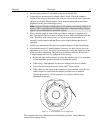
3. If you haven’t already done so, install a lens on the camera. If the I-PentaMAX is to
be operated with a microscope, see Chapter 6 and follow the directions there. Begin
with the lens capped, with a small aperture setting, and with the focus set to
approximately the anticipated distance of the subject.
4. On the IIC-200 (IIC-300, IIC-100, or pulser equipped with an MCP-100):
• Set the MCP GAIN dial to its lowest setting. (Full counterclockwise for the
IIC-200 or IIC-100).
• Set the SHUTTER/GATE switch to "GATE".
• Set the AUTOBRIGHT CONTROL (BRIGHT CONTROL) switch to "OFF".
• Set the MCP POWER switch to "OFF".
5. Turn on the power to the I-PentaMAX, the computer, and the IIC-200 (IIC-300,
IIC-100, or pulser equipped with an MCP-100).
Do not turn on the MCP POWER switch at the IIC-200 (IIC-300, IIC-100, or MCP-100
module) yet.
The I-PentaMAX Camera power On/Off switch is located immediately above the
line-cord socket on the back of the Temperature/Power Supply. As soon as the power
WARNING!
CAUTION