


Appendix E Virtual Chip Mode 97
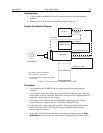
Controller/CCD tab card
• Controller: PentaMAX
•
Controller Version: 5
•
CCD Type: appropriate frame transfer array (EEV 512x512FT, for this
procedure)
•
Shutter Type: None
•
LOGIC OUT Output: Shutter
•
Readout Mode: Frame Transfer
Interface tab card
•
Type: the appropriate interface card. For this procedure, the selection is
High Speed PCI.
Cleans/Skips tab card
•
Number of Cleans: 1
•
Number of Strips per Clean: 512
•
Minimum Block Size: 2
•
Number of Blocks: 5
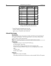
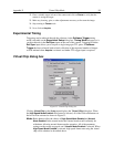
16. From the Setup menu, select Virtual Chip, and enter the following settings:
• High Speed Mode Enabled
• Virtual Chip Definition: The settings below assume a 41x41 pixel virtual
chip. The X and Y dimensions are established by the external mask. The
virtual chip is fully flexible in the X direction. However, the set of choices
for the Y-dimension has been pre- selected for optimal performance. Note
that the origin point that Princeton Instruments uses for a CCD array is 1,1.
•
Chip Y Dimension: 41. Select this dimension from the drop down list.
•
Chip X Dimension: 41. Enter this dimension manually.
17. Click on the Load Default Values button. This enters the default ROI values. These
values are: Start pixels of 1,1; End pixels based on the Chip Y and Chip X
dimensions; and Groups of 1.
• Region of Interest: The settings below assume a 41x41 pixel ROI (i.e., the
entire
virtual chip). An ROI that is a subset of the virtual chip can be defined.
X Start: 1 Y Start: 1
X End: 41 Y End: 41
X Group: 1 Y Group: 1
• Click on the
Download Virtual Chip Definition button. This will download
the definition, set up the ROI, and calculate the readout time.