


96 I-PentaMAX System Manual Version 3.A
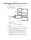
6. Connect the Camera-Power Supply cable to the TO CAMERA connector on the
rear of the Temperature/Power supply unit and to the
FROM POWER SUPPLY
connector at the rear of the camera. Tighten down the locking screws.
7. If it has not been installed already, connect a line cord from the Power Input assembly
on the back of the Temperature/Power supply unit to a suitable AC power source.
8. Reconfirm that the IIC-200
POWER switch is set to "OFF".
The high voltage cable carries lethal voltages to the image intensifier (as much as 10,000
Volts). Never turn on the high-voltage power supply (IIC-100, IIC-200, or IIC-300) or a
pulser equipped with the MCP-100 modular high-voltage supply unless both ends of the
high voltage cable are connected. A cable connected at one end only is not only
hazardous, but is susceptible to arcing and subsequent erratic operation due to the
formation of carbon tracks.
The high voltage cable should be handled with care. Dropping the cable or banging the
connectors may damage the pins, resulting in a poor or intermittent connection.
9. Connect the HV Supply cable to the HV output connector on the rear of the IIC-200
and to the HV input connector on the nose of the camera. To ensure proper electrical
connection:
a. Tighten the cable connector a couple of turns and then push down on the
connector collar.
b. Repeat the tightening and pushing down until the cable connector is fully
seated.
c. Repeat Steps a-b for the other end of the cable.
10. If it has not been installed already, connect a line cord from the Power Input assembly
on the back of the IIC-200 to a suitable AC power source.
11. OPTIONAL. Connect a 75 Ω BNC cable from the
SHUTTER IN connector on the
rear of the IIC-200 to the
LOGIC OUT connector on the rear of the camera. This
setup is required for exposure times < the readout time.
12. Turn on the Temperature/Power Supply unit and set the temperature ( -20°C is the
coldest setting) and wait until the temperature locks.
13. Following the intensifier precautions in this manual and in the IIC-200 manual, press
the IIC-200
POWER switch to "ON".
a. Verify that the MCP GAIN setting is "0".
b. Set the
MCP POWER/OFF switch to "MCP POWER". The audible intensifier
alarm should beep when the high voltage is applied. If it continues to beep,
switch
MCP POWER/OFF back to "OFF" and contact Princeton Instruments
Technical Support.
c. Leave
SHUTTER/GATE switched to "GATE" and AUTOBRIGHT/CONTROL
switched to "
OFF".
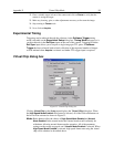
14. Turn on the host computer and select the WinView/32 icon.
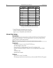
15. From the Setup menu, select Hardware, and enter the following settings:
DANGER
WARNING!