


Appendix E Virtual Chip Mode 95
Assumptions:
• You are familiar with the WinView/32 software and have read the hardware
manuals.
• Masking is for a 41x41 pixel Virtual Chip with its origin at 1,1.
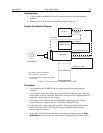
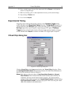
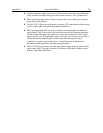
System Connection Diagram:
FROM POWER SUPPLY
HOST COMPUTER
LOGIC OUT**
HV CABLE
EXPERIMENT
TEMPERATURE/
POWER SUPPLY
IIC-200
TO CAMERA
SHUTTER IN *
INTENSIFIER
H.V.P.S
I-PENTAMAX
HIGH SPEED SERIAL (TAXI)
INTERFACE CARD
* This cable connection is required
when exposure < readout time.
λ
**This connector may be labeled NOTSCAN
on older units.
Figure 32. System Diagram: I-PentaMAX with IIC-200
Procedure:
1. Verify that the power is OFF for ALL system components (including the host
computer).
2. Verify that the correct line voltages have been selected and that the correct fuses have
been installed in the IIC-200 Image Intensifier Controller and the Temperature/Power
supply unit (autoselecting for line voltage).
3. Verify that the HV connectors on the I-PentaMAX camera and the IIC-200 have
identical labels (for example, both say "USE ONLY WITH GEN III").
4. In the center panel on the front panel of the IIC-200, put all of the switches in their
DOWN positions (GATE, OFF, and OFF) and turn the MCP GAIN dial fully
counter-clockwise (0 gain).
5. Connect the TAXI cable to the interface card at the host computer and to the
High
Speed Serial
connector at the rear of the camera. Tighten down the locking screws.