


64 I-PentaMAX System Manual Version 3.A
Note: Do not be concerned about either the DC level of this background or its shape
unless it is very high, i.e., > 200 counts. What you see is not noise. It is a fully
subtractable readout pattern. Each CCD has its own dark charge pattern, unique to that
particular device. Simply turn off the intensifier and then acquire and save a dark charge
“background image” under conditions otherwise identical to those used to acquire the
“actual” image. Subtracting the background image from the actual image will
significantly reduce dark-charge effects.
If you have not just changed the temperature setting, a sudden change in the baseline
signal may mean excessive humidity in the intensifier enclosure of the camera. If you
observe this type of change, turn off the system immediately. An excess humidity
condition should be corrected promptly or permanent damage not covered by the
Warranty could occur. Have the unit serviced by Princeton Instruments or an authorized
service facility of Princeton Instruments.
Readout of the Array
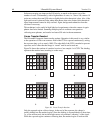
In this section, a simple 6 × 4 pixel CCD is used to demonstrate how charge is shifted
and digitized. As described below, two different types of readout are available. Full
frame readout, for full frame CCDs, reads out the entire CCD surface at the same time.
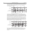
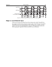
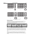
Frame transfer operation assumes half of the CCD is for data collection and half of the
array is a temporary storage area.
Full Frame Readout
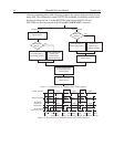
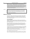
The upper left drawing in Figure 24 represents a CCD after exposure but before the
beginning of readout. The capital letters represent different amounts of charge, including
both signal and dark charge. This section explains readout at full resolution, where every
pixel is digitized separately.
Readout of the CCD begins with the simultaneous shifting of all pixels one column
toward the “shift register,” in this case the column on the far right. The shift register is a
single line of pixels along one side of the CCD, not sensitive to light and used for
readout only. Typically the shift register pixels hold twice as much charge as the pixels
in the imaging area of the CCD.
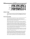
After the first column is moved into the shift register, the charge now in the shift register
is shifted toward the output node, located at one end of the shift register. As each value is
“emptied” into this node it is digitized. Only after all pixels in the first column are
digitized is the second column moved into the shift register. The order of shifting in our
example is therefore D6, C6, B6, A6, D5, C5, B5, A5, D4....
After charge is shifted out of each pixel the remaining charge is zero, meaning that the
array is immediately ready for the next exposure.
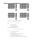
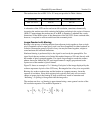
Below are the equations that determine the rate at which the CCD is read out. Tables of
values for CCDs supported at the time of the printing of this manual also appear below.
CAUTION