


49
Chapter 7
Intensifier
Overview of Intensifier Operation
The modern image intensifier results from a concerted effort undertaken to develop night
vision capabilities for military applications and to this day the primary application
remains night vision – the ability to see in low light level conditions. Basically, an
intensifier is a four-electrode vacuum-tube device having a photocathode (at the input), a
microchannel plate (for increased gain), and a phosphor screen (at the output). There are
two types of intensifiers: inverter and proximity focused. The inverter type
electrostatically focuses and inverts the image inside the tube. The proximity-focused
type has all of the elements closely spaced, has no need for focus electrodes, and is much
more compact. I-PentaMAX has a proximity focused type intensifier that is fiberoptically
coupled to the CCD (1.5:1 taper ratio).
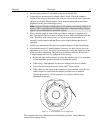
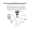
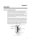
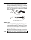
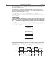
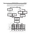
Figure 12 shows a schematic of an image intensifier tube. Photons admitted to the tube
strike the photocathode, which then emits photoelectrons in response. The electrons are
accelerated across a half millimeter gap by an acceleration potential to the microchannel
plate (MCP). When an electron enters the microchannel, it gets amplified by the voltage
difference between the front and back surfaces of the microchannel plate. The electron
becomes an electron packet as it travels down the channel. When the electron packet
exits the rear of the microchannel, it is pulled across a small gap to a phosphor screen by
a proximity focusing voltage of approximately 5 kV. There, the kinetic energy of that
electron packet is converted into visible photons by the phosphor. The photons in turn
exit the tube via the fiber-optic stub and strike the CCD array.
Electrical Connection Rings
Intensified Image
Fluorescent Screen
Photocathode
Microchannel Plate (MCP)
Incident Light
-200 V
0 V
600 V - 900 V
8 kV
Figure 12. Image Intensifier Tube