Chapter 5 First Light 39
is turned on, the POWER light at the front panel of the Temperature/Power Supply
unit should light.
6. Start the application software (WinView, for example).
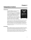
7. At the front panel of the Temperature/Power Supply, set the temperature display
mode switch to SET POINT and the Temperature Control ON/OFF switch to ON.
As soon as this switch is set to ON, the yellow STATUS indicator should light,
indicating that the temperature control loop is functioning but that temperature lock
has not yet been attained.
8. Adjust the TEMP SET dial for a display indication of -20.0°. Then set the
temperature display mode switch to ACTUAL. The indicated temperature should
drop steadily, reaching -20° in about ten minutes (typical). At that point the yellow
Status indicator will extinguish and the green one will light. Note that some
overshoot is normal, which could cause the Status indicators to toggle, that is, the
yellow indicator may come on again briefly. Should this happen, the displayed
temperature will quickly return and stabilize at -20.0°. There may be a small
difference, typically 0.1°, between the displayed set and locked temperatures. This is
normal and does not indicate a system malfunction.
9. Completely block light access into the camera. Then double check the system
connections.
Note: You may want to run the camera and monitor the dark current pattern while
the array is cooling down.
10. When satisfied that there are no errors, set the MCP POWER switch on the IIC-200
(IIC-300, IIC-100, or MCP-100 module) to the ON position. The audible intensifier
alarm should sound briefly as the high voltage is applied. Verify that the MCP GAIN
setting is "0": the voltage is set with the MCP GAIN dial.
Notes:
Gen II intensifiers typically function optimally with a voltage in the range of 700 V
to 800 V. Gen III intensifiers typically require a higher voltage, sometimes as high as
1000 V, and a higher setting will be required. Some experimentation may be required
to find the optimum setting for your intensifier.
The MCP GAIN dial is not calibrated; however, a relative gain report is provided
with the system. This report equates dial setting (from 0-100, in increments of 10)
and counts/photoelectron.
The MCP-100 CANNOT be used with a Gen III intensifier.
A standard IIC-100 cannot normally be set to the higher voltage required by a Gen III
intensifier. High-voltage power supplies shipped with systems having a Gen III
intensifier are factory-adjusted so that they can be set to the higher voltage. If you
have more than one system, take care that the intensifier and high-voltage power
supplies are not interchanged.
In the case of a PG-200 pulser equipped with an MCP-100 module, there is no way
to set the MCP voltage with the system unpowered. The MCP voltage defaults to
~500 V and will need to be adjusted to the required level once the system is
powered.


