


English 9
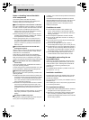
3 INSTALLATION AND CONNECTIONS
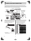
This section describes how to connect the digital video recorder to the CCTV camera and other devices. Be sure to read the
instruction manuals for each connected device. Make connections carefully. Improper connections can cause smoke or malfunctions.
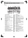
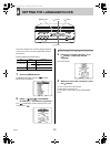
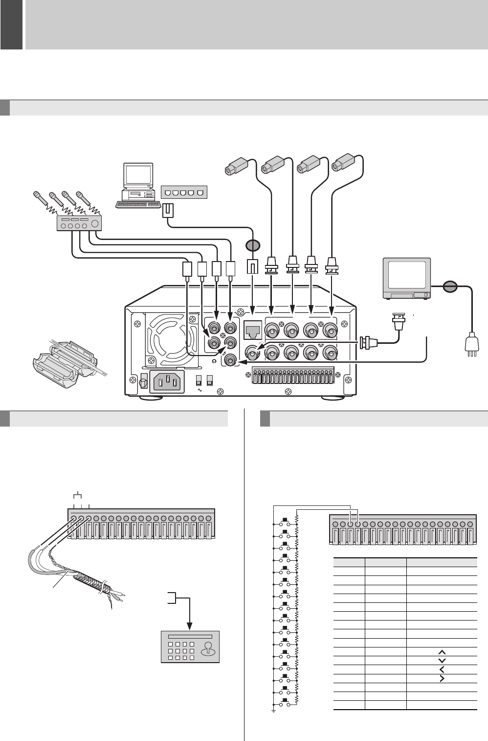
The connections for cameras (4), TV monitor (1), microphone and PC are shown below.
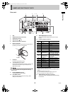
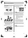
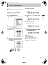
The connections for a system controller are shown below.
Use a twisted-pair cable (sold separately) to connect rear
panel control terminals A, B and C (ground). Connect
signal A to signal A, and signal B to signal B.
z Twisted-pair cable
Can reduce interference on the signal caused by noise
generated by other cables.
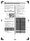
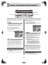
The connections for a remote control circuit are shown
below. Making the connections shown below lets you
operate the digital video recorder by remote control.
z Create the remote control circuit shown in the
illustration, and connect it to the remote control input
terminals (among the control terminals).
Use a resistance of 1/10 ohms or more and with a D
ranking (precision 0.5% or finer).
Basic connections
AUDIO
IN
3
4
1
2
OUT
LAN
1
123456789
10 11 12 13 14 15 16 1718 19
234
1234
IN
OUT
MONITOR OUT
AC IN
VIDEO
ALL
RESET
ON
NTSC
PAL
TV SYSTEM
RS-485
TERMINATE
OFF
PC
(sold separately)
or
switching hub
(sold separately)
Amp (sold
separately)
CCTV camera (sold separately)
TV monitor
(sold separately)
Video input terminal
*1 Use a shielded LAN
connection cable, and
wind it once around the
supplied ferrite core.
Microphone
(sold separately)
*2 Attach the supplied ferrite
core to the base of the
TV monitor power cable
(coiling not necessary).
*1
*2
Audio input
terminal
System controller connections
123456789
10 11 12 13 14 15 16 17 18 19
RS-485
ABC
To signal B
To signal A
Twisted-pair cable
Ground
RS-485 terminal
System controller
(sold separately)
Connecting a remote control circuit
123456789
10 11 12 13 14 15 16 17 18 19
220
220
300
360
470
680
820
1.2k
1.8k
2.2k
3.3k
4.7k
7.5k
13k
27k
68k
SW 1
SW 2
SW 3
SW 4
SW 5
SW 6
SW 7
SW 8
SW 9
SW 10
SW 11
SW 12
SW 13
SW 14
SW 15
SW 16
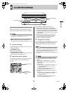
Key
Resistance Function
SW1
220
Ω
Camera 1
SW2
440
Ω
Camera 2
SW3
740
Ω
Camera 3
SW4
1100
Ω
Camera 4
SW5
1570
Ω
QUAD/SEQ
SW6
2250
Ω
AUDIO SELECT
SW7
3070
Ω
SEARCH
SW8
4270
Ω
MENU
SW9
6070
Ω
EXIT/OSD
SW10
8270
Ω
SW11
11570
Ω
SW12
16270
Ω
SW13
23770
Ω
SW14
36770
Ω
STILL
SW15
63770
Ω
PLAY
SW16
70570
Ω
REC
e00_l8hbc_hd_6.book Page 9 Wednesday, July 30, 2003 2:34 PM