


English 7
2 NAMES AND FUNCTIONS OF PARTS
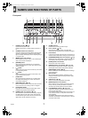
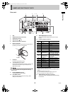
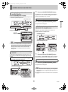
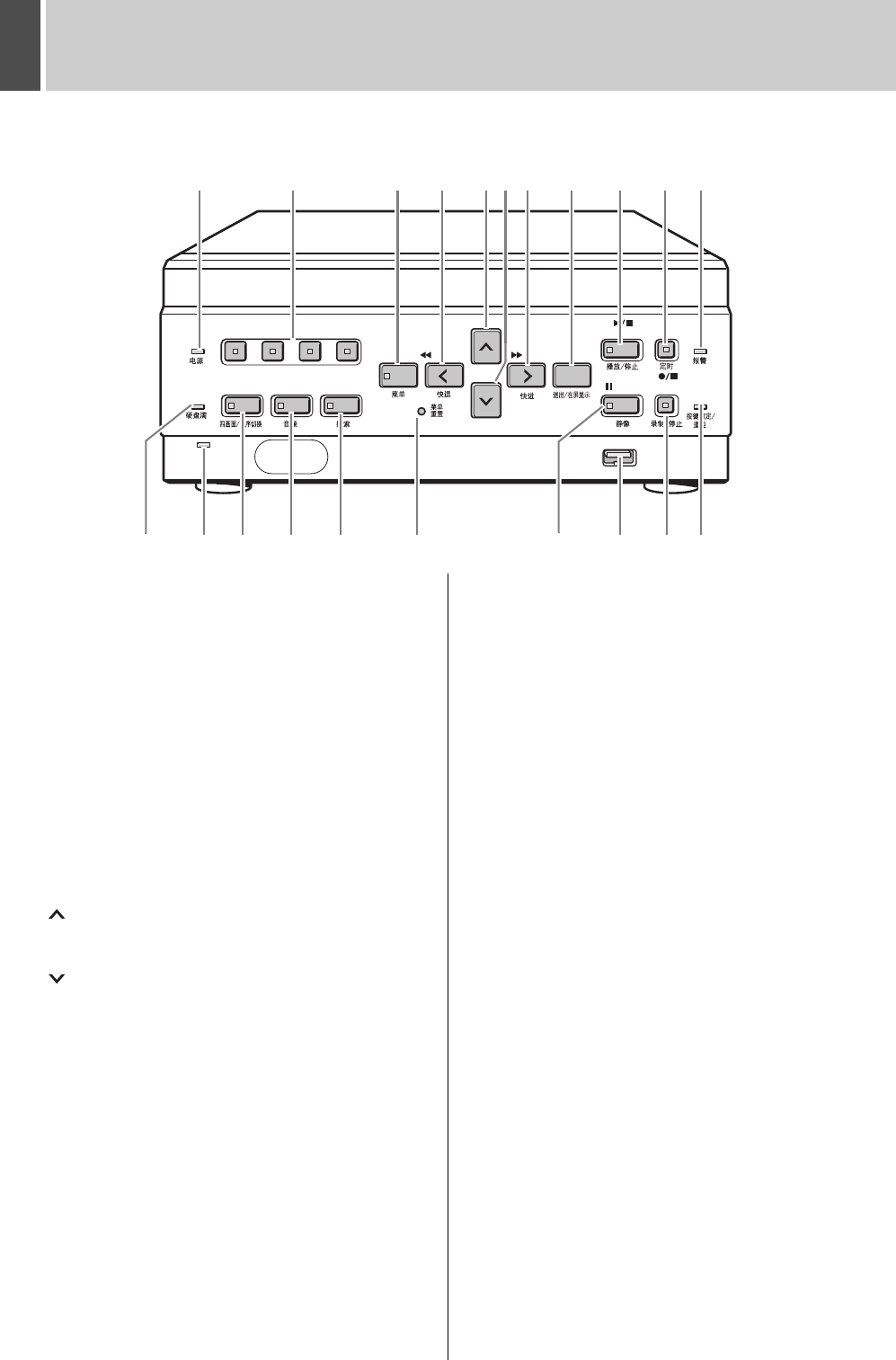
Front panel
1. POWER indicator (JP. 10)
Lights when the power is ON.
Flashes when there is a problem with the hard disk or
fan.
2. CHANNEL buttons and indicators
Used when switching the image display from the quad
screen to a single screen. Pressing a channel button
lights its indicator and displays the corresponding image
in a single screen.
3. [MENU] button and indicator
Used to display the menu screens. The indicator lights
when a menu screen is displayed.
4. [REVIEW] button
When pressed during playback, lets you rewind the
image while watching it on screen. Also used for menu
screen operations.
5. [ ] button
Used to move the cursor in menu screens up. Also used
to change setting values.
6. [ ] button
Used to move the cursor in menu screens down. Also
used to change setting values.
7. [CUE] button
When pressed during playback, lets you fast-forward
the image while watching it on screen. Also used for
menu screen operations.
8. [EXIT/OSD] button (JP. 23)
Returns the display to the normal screen when the main
menu, a sub-menu, or a setting screen is displayed.
9. [PLAY/STOP] button
Plays back the normal image (indicator lights). When
pressed during playback, stops playback.
10. [TIMER] button and indicator (JP. 15)
When the button is pressed while recording or stopped,
the digital video recorder enters timer record standby,
and the indicator lights. When the set time arrives, the
digital video recorder starts timer recording.
11. ALARM indicator
Flashes when recording an alarm image.
12. FULL indicator (JP. 33)
Lights when the remaining memory in the hard disk’s
recording area has reached zero and recording has stopped.
13. LAN indicator
Lights when the digital video recorder is connected to a
network. Flashes when data is being sent and received.
14. [QUAD/SEQUENCE] button and indicator
(J
P. 12)
Switches to the quad screen display, or switches from the quad
screen display to each single-screen display in sequence.
15. [AUDIO] button and indicator
Switches the audio output channel.
16. [SEARCH] button and indicator (JP. 19, P. 20)
When the button is pressed while recording or stopped, the
indicator lights, and the search setting screen is displayed
17. [MENU RESET] button (JP. 23)
Used to initialize the currently displayed menu settings,
and to set the time.
18. [STILL] button
When pressed during playback, freezes the screen
image (the indicator lights). Pressing the button again
resumes playback.
19. USB terminal (JP. 48)
Used to connect a CompactFlash card reader.
20. [REC/STOP] button and indicator
Starts normal recording. Indicator lights during recording.
During recording, pressing the button for at least 3
seconds stops recording and turns off the indicator.
21. LOCK/REMOTE indicator (JP. 22, P. 44)
Lights when operations have been locked by the key
lock or security lock setting.
If an operation button is pressed when the security lock
is set, a buzzer sounds. The key lock cannot be set
during playback.
The indicator flashes at 4Hz when there is a network
connection, and flashes at 1Hz when there is a network
connection while locked.
1234
POWER
FULL
AUDIO SEARCH
MENU
USB
TIMER
ALARM
EXIT/OSD
MENU
RESET
REVIEW CUE
LOCK/
REMOTE
PLAY/STOP
REC/STOPSTILL
QUAD/
SEQUENCE
LAN
(LINK/ACT)
1110987654321
2120181716151412
1913
e00_l8hbc_hd_6.book Page 7 Wednesday, July 30, 2003 2:34 PM