


NAMES AND FUNCTIONS OF PARTS2
8 English
INTRODUCTION
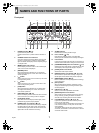
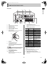
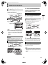
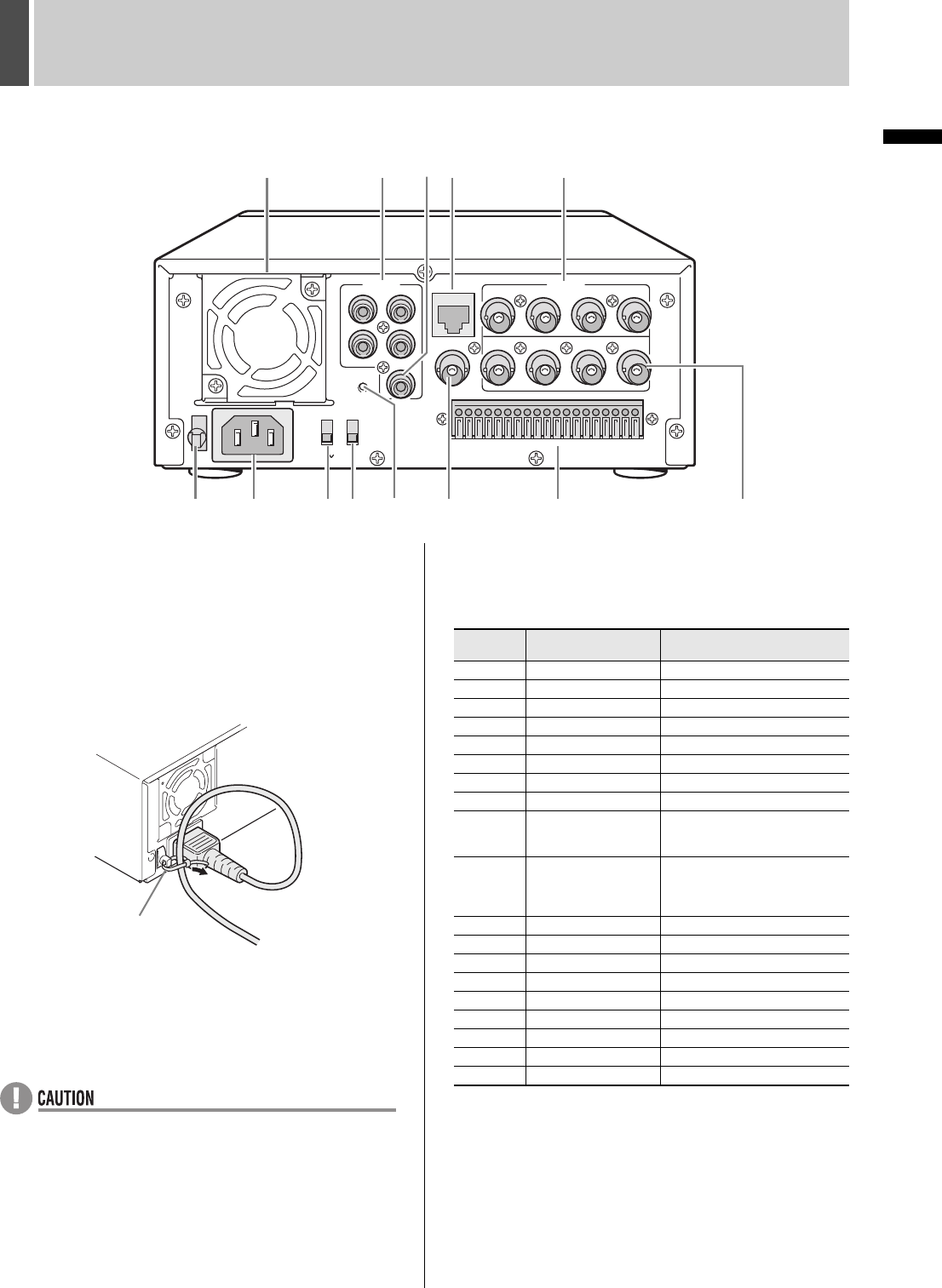
Rear panel
1. FAN
2. AUDIO IN terminals (4 channels)
3. AUDIO OUT terminal
4. LAN terminal (JP. 45)
5. VIDEO IN terminals (4 channels)
6. Power cord holder
Secure the power cord to the holder using the cord tie
(accessory) as shown in the illustration.
7. AC INLET
AC power input terminal (3-core)
8. TV SYSTEM selector switch
Used to select between NTSC and PAL systems for the
camera input and monitor output connected to the
digital video recorder.
z Turn the power OFF then ON again after selecting
NTSC or PAL.
9. RS-485 TERMINATE switch
Turns RS-485 termination ON/OFF.
10. ALL RESET switch
Resets the clock and backup mode setting. (Menu
settings are maintained)
11. VIDEO MONITOR OUT terminal
Output terminal that displays quad screen on single
monitor.
12. Control and alarm terminals
*1 Used for twisted-pair cable connection.
*2 SERIES REC outputs NON REC OUT when SERIES REC is
“OFF”.
*3 The following warnings are output:
z Hard disk drive error z Fan error z Recording error
z No input signal when VIDEO LOSS is ON.
13. VIDEO OUTPUT terminals (4 channels)
Terminals for output of individual video channels directly
to the monitor.
AUDIO
IN
3
4
1
2
OUT
LAN
1
123456789
10 11 12 13 14 15 16 17 18 19
234
1234
IN
OUT
MONITOR OUT
AC IN
VIDEO
ALL
RESET
ON
NTSC
PAL
TV SYSTEM
RS-485
TERMINATE
OFF
1 234 5
67 91011 12 138
Cord tie
Terminal
No.
Pin Signal
1 RS485A
To RS-485 terminal signal A *
1
2 RS485B
To RS-485 terminal signal B *
1
3 C Common
4 REMOTE Remote Control terminal
5 C Common
6 CLOCK ADJ IN Input for clock setting
7 CLOCK ADJ OUT Output for clock setting
8 C Common
9 SERIES REC IN
Input terminal used when
recording with multiple digital
video recorders connected.
10
NON REC OUT/
SERIES REC OUT
Output terminal used when
recording with multiple digital
video recorders
connected.
*
2
11 ALARM IN 1 Alarm input for channel 1
12 ALARM IN 2 Alarm input for channel 2
13 ALARM IN 3 Alarm input for channel 3
14 ALARM IN 4 Alarm input for channel 4
15 ALARM RESET Alarm reset input
16 ALARM OUT Alarm output
17 C Common
18 WARNING OUT Warning output *
3
19 DISK FULL OUT Recording area full warning
e00_l8hbc_hd_6.book Page 8 Wednesday, July 30, 2003 2:34 PM