


Chapter 1 Overview 27 (GB)
Chapter 1 Overview
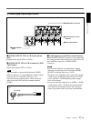
1 AUDIO OUTPUT CH-1 to CH-4 jacks (phono
jack)
Outputs audio signals (CH-1 to CH-4).
2 AUDIO INPUT CH-1 to CH-4 connectors (XLR
3-pin, female)
Inputs audio signals (CH-1 to CH-4).
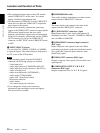
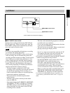
Note
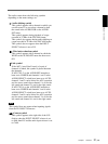
The unit employs electronically balanced AUDIO
INPUT connectors. To input unbalanced audio signals
(a phono jack of a consumer VCR, etc.), use a
conversion cable as shown below. (This conversion
cable shorts the COLD and the common terminal
(GND)).
2
1
3
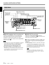
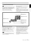
2 Audio signal input/output section
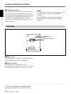
3 Audio input level (–60/–20/+4) control selectors
When the INPUT SELECT selector is set to other than
DV, select an audio input signal level (–60/–20/+4) for
the CAMERA connector or AUDIO INPUT
connectors.
Notes
• If this switch setting is not appropriate, clipping
distortion or noise may occur even if the AUDIO
SELECT switch has been set to AUTO.
• The unit is not compatible with a camera that outputs
+4 dB. If you set the audio input selectors to CAM,
select –60 dB or –20 dB depending on the output
level of the camera.
• If you can select the output level (–60 dB or –20 dB)
on the camera, select –20 dB on the camera and the
unit. When the unit and the camera are connected
with a long camera cable, noise may be minimized.
1 AUDIO OUTPUT
jacks
2 AUDIO INPUT connectors
3 Audio input level control
selectors
4 Audio input selectors
HOT
COM (GND)
COLD
Signal
GND