


Adjusting Signals
Chapter 4 Setting the Time Code and Adjusting the Video Signals
68 (GB) Chapter 4 Setting the Time Code and Adjusting the Video Signals
Adjusting the chrominance signal gain level of the composite signal
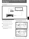
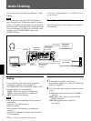
1 Play back a tape to output the signals from the
VIDEO OUT2 connector.
The vectorscope displays the picture.
2 Adjust the chrominance signal gain level in PB
OUTPUT in VIDEO LVL on the VIDEO SET
menu.
For details on “PB OUTPUT”, see “VIDEO SET
menu” on page 85 (GB).
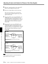
Adjusting the Input Level
Adjusting the camera component signal
level
1 Set the INPUT SELECT selector to CAMERA.
2 Stop the unit and set it to the EE mode.
The waveform monitor displays the picture.
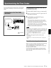
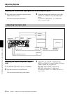
Reference
signal generator /
Camera
or
or
DSR-50/50P
S VIDEO
IN
VIDEO/
REF.IN
CAMERA
VIDEO OUT2
COMPONENT OUTPUT
Composite
video input
Component
input
Waveform monitor
Composite
video output
Composite
video input
Vectorscope
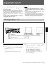
3 Adjust the Y, R-Y, and B-Y signal levels in
INPUT in VIDEO LVL on the VIDEO SET menu.
Y LVL: Adjusts the Y signal level.
R-Y LVL: Adjusts the R-Y signal level.
B-Y LVL: Adjusts the B-Y signal level.
For details on “INPUT”, see “VIDEO SET menu” on
page 85 (GB).