


36
Superimposed Character Information
Chapter 3 Preparations
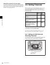
3-8 Superimposed
Character Information
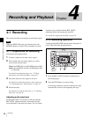
When CHARACTR on the HOME page of the function
menu is set to ON, the video signal output from the HD SDI
OUTPUT (SUPER) connectors, SDI OUT 2 (SUPER)
connector, or COMPOSITE OUT 2 (SUPER) connector
contains superimposed character information, including
timecodes, menu settings, and alarm messages.
Adjusting the character display
You can adjust the position, size, and type of the
superimposed characters using setup menu items 002, 003,
005, 009, 011, and 012.
For details on setup menu items 002, 003, 005, 009, 011,
and 012, see page 63 and page 64.
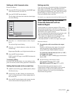
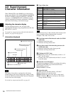
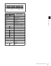
Information displayed
The display shown above corresponds to the factory
default settings of the unit. Changing the setting of setup
menu item 005 allows different time data to be displayed
on the lower line of the display.
For details on setup menu item 005, see page 63.
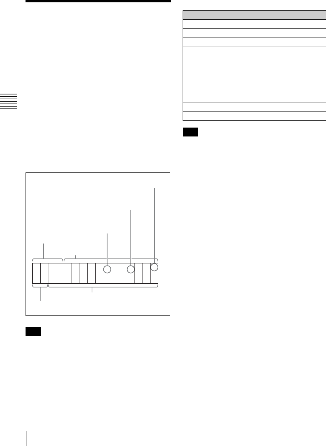
a Type of time data
If the time data or user’s bits cannot be read correctly, each
item in question will be displayed with an asterisk.
Example: T*R, U*R, T*R. or U*R.
b Drop frame mark of the timecode reader (for 59.94i
mode only)
“.”: Indicates drop frame mode
“:”: Indicates non-drop-frame mode
c Drop frame mark of the timecode generator (for
59.94i mode only)
“.”: Indicates drop frame mode (factory preset)
“:”: Indicates non-drop-frame mode
d Field mark of VITC data
(blank): Fields 1 and 3 (for 59.94i mode) or fields 1, 3, 5
and 7 (for 50i mode)
“*”: Fields 2 and 4 (for 59.94i mode) or fields 2, 4, 6 and
8 (for 50i mode)
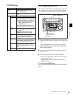
e Selection of recorder/player
The indication changes as follows, according to the setting
for R/P on the P5 EDIT page of the function menu:
P: PLAYER is selected.
R: RECORDER is selected.
f Operation mode
The field is divided into three blocks: A, B and C.
Block A: Displays the operation mode.
Block B: Displays the servo lock status or tape speed.
Block C: Displays a x mark to indicate an edit section
during automatic editing.
Note
TCR . 23 : 59 . 40 . 18
*
PSHUTTLESTILL
4 Field mark of VITC data
3 Drop-frame mark of the
timecode generator
1 Type of time data
Time data
2 Drop-frame mark of the
timecode reader
6 Operation mode
5 Selection of recorder/player
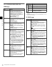
Display Meaning
CTL Data of the CTL counter
TCR Timecode read by the LTC reader
UBR User’s bit read by the LTC reader
TCR. Timecode read by the VITC reader
UBR. User’s bit read by the VITC reader
TCG Timecode generated by the timecode
generator
UBG User’s bit generated by the timecode
generator
IN IN point
OUT OUT point
DUR Duration between the IN and OUT points
Note