


Chapter 7 Menus
72
7-2 Basic Setup Menu
7-2 Basic Setup Menu
7-2-1 Items in the Basic Setup Menu
The basic menu items (excluding the items related to the
digital hours meter) are listed in the following table.
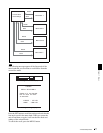
• Item names are the names which appear in the image
display.
An abbreviated name appears in the time data display
section when you press the NEXT button.
• The values in the Settings column are the values which
appear in the time data display section. (The values may
appear in a different format in the image display. In this
case, the image display values are shown in
parentheses.) Underlined values are the factory defaults.
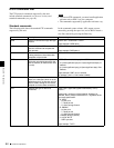
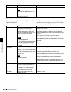
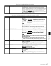
Item
number
Item name Settings
001 PREROLL TIME 0 s (0 sec)... 5 s (5 sec)
... 30 s (30 sec): Set the preroll time to between 0 and 30
seconds in steps of 1 second.
A preroll time of at least 5 seconds is recommended when using this unit for
editing.
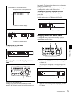
002 CHARACTER H-POSITION Adjust the horizontal screen position (as a hexadecimal value) of the text information
output from the VIDEO OUT connector and SDI OUT connector for superimposed
display on the monitor.
00... 0A
...2A (525(U)/525(J) line modes) /00... 09 ...29 (625 line mode): The
hexadecimal value 00 is for the far left of the screen. Increasing the value moves
the position of the characters to the right.
Set this item by adjusting to the required position while viewing the monitor.
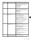
003 CHARACTER V-POSITION Adjust the vertical screen position (as a hexadecimal value) of the text information
output from the VIDEO OUT connector and SDI OUT connector for superimposed
display on the monitor.
00... 2E
...38 (525(U)/525(J) line modes)/00... 37 ...43 (625 line mode): The
hexadecimal value 00 is for the top of the screen. Increasing the value lowers the
position of the characters.
Set this item by adjusting to the required position while viewing the monitor.
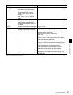
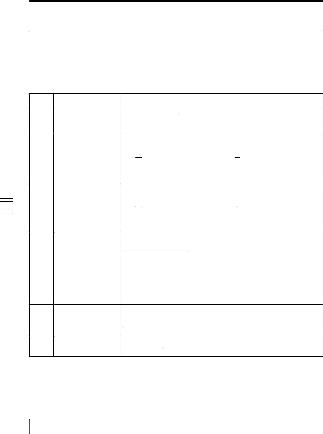
005 DISPLAY INFORMATION
SELECT
Determine the kind of text information to be output from the VIDEO OUT connector
and SDI OUT connector.
T&sta (time data & status)
: Time data and the units status.
T&UB (time data & UB): Time data and user bit data. (When UB (user bit data) is
selected with the COUNTER button, the user bit data and time data arranged in
that order are displayed.)
T&CNT (time data & CNT): Time data and counter count. (When COUNTER is
selected with the COUNTER button, the counter count and time data arranged in
that order are displayed.)
T&T (time data & time data): Time data and time code (TC or VITC).
T&clp (time data & clip name): Time code and clip name
time (time data only): Time data only.
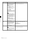
006 LOCAL FUNCTION
ENABLE
Determine which recording and playback control buttons on the control panel are
enabled when this unit is controlled from external equipment.
dis (all disable): All buttons and switches are disabled.
st&ej (stop & eject)
: Only the STOP button and EJECT button are enabled.
ena (all enable): All buttons and switches are enabled.
007 TAPE TIMER DISPLAY Determine whether to display the counter in 12-hour mode or 24-hour mode.
+ –12H (+/–12H)
: 12-hour mode
24H: 24-hour mode