4-15
Servicing Precautions
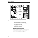
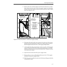
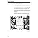
5. At the top of the circuit board containing the indicator LEDs, reconnect
the multiwire connector that you previously disconnected.
6. Reconnect the two plugs to the jacks at the top of the compartment.
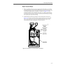
If this is the upper power supply in a redundant system, connect the
corresponding plugs in the lower supply to their mates in the bottom
of this supply.
7. Turn on the power supply.
8. Adjust the voltages, as in the Primary and Redundant Power Supply
Voltage Adjustments procedure in Section 2 of this manual.
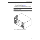
9. Reinstall the left and right rear access panels of the power supply.
10. If this is a redundant power system:
a. You must first replace the Multi-Output power assembly in the
second Power Supply frame (if it is not a Todd supply) by repeating
the procedure given above.
b. When you have completed the installation (of both Multi-Output
supplies, if required), reconnect the power source and apply power
to both units.
c. Before you install the rear plates on the Power Supply frames, you
must adjust the output voltages for load-sharing. Refer to the
Primary and Redundant Power Supply Voltage Adjustments
procedure in Section 2 of this manual.
Replacement of +5 Volt Power Supply Assembly
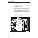
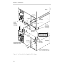
The following procedure describes replacing a Pioneer +5 Volt power
supply assembly with a Todd power supply assembly.
For any of the other three possible replacements—replacing a Pioneer unit
with a Pioneer, replacing a Todd unit with a Todd, or replacing a Todd unit
with a Pioneer—use the following procedure as a guide and perform the
appropriate steps.


