2-67
Cable Connections
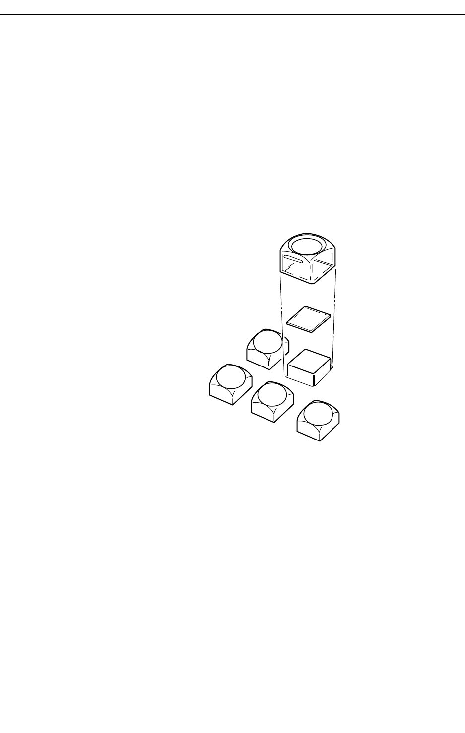
Remote Aux Panel Lens Chip Installation
The primary crosspoint push-buttons on the 2-RU and 3-RU control panels
can be labeled as desired. An envelope containing a set of printed lens
chips is shipped with the control panel.
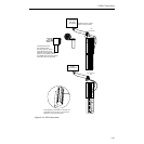
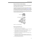
To change a lens chip, grasp the lens firmly with your fingers and pull it
straight out. The push-button may come off with the lens. You can then
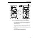
pull apart the push-button, lens, and lens chip (refer to Figure 2-35). When
re-inserting the push-button and lens into the panel, make sure to align the
keys on the legs of the push-button base with the larger key slots on the
base of the switch (not the smaller slots at the top of the switch, near the
lamp). When properly installed, the push-button should lock in place and
not rotate around the lamp and switch.
Remote Aux Panel Power Up
1. Turn OFF the power to the switcher frame.
2. Attach the Communications Bus Cable(s) and the Power Supply cable
to the connectors on the rear of the Remote Aux Panel.
3. Using standard rack-mounting screws and washers (not supplied),
install the Remote Aux Panel in the equipment rack.
4. Plug the Remote Aux Panel power supply into the AC power source
(100–120 VAC or 200–240 VAC).
5. After all panels have been connected, plug the D connector on the
Communications Cable into connector J4 on the Communications I/O
module at the rear of the switcher.
6. Turn the switcher frame’s power on.
Figure 2-35. Lens Chip Installation
Clear Overcap
Lens Designation Chip
Lens


