2-65
Cable Connections
Connector Installation
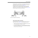
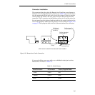
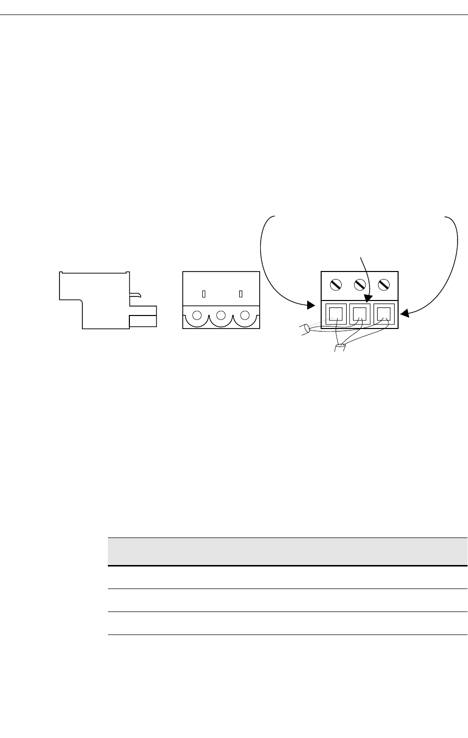
The connector that plugs into the Remote Aux Panel has screw clamps to
hold the wires. Paying attention to polarity (see Table 2-5), insert the wires
into the appropriate holes and screw down the clamps. If there is another
control panel, the cable to the next panel must also be inserted into this
connector. The D connector on that cable must be cut off, and the wires for
the next panel must be stripped and inserted into the same holes before the
screws are tightened. Make sure the polarity is correct. Refer to Figure 2-18
on page 2-37and plug the cable into the Communications Bus connector.
If you are building your own cable, use a shielded twisted-pair such as
Belden 8451 and refer to Table 2-5.
Table 2-5. Cable Polarity
Panel Connector D-Connector Factory Supplied Cable
+ (Plus) 3 and 7 Red
– (Minus) 2 and 8 Black
Shield 9 Shield
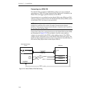
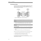
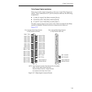
Figure 2-32. Remote Aux Panels Connection
KEEP SHIELD CONNECTION AS SHORT AS POSSIBLE
From Switcher or
Previous Panel
To Next Panel
(if any)
To Pin 9 of
D Connector
(SHIELD)
To Pins 2 and 8 of
D Connector (–)
To Pins 3 and 7 of
D Connector (+)


