


6 F 3 B 0 3 6 4
123
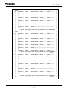
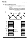
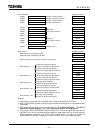
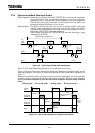
5.3.2 Asynchronous Mode Data Input/Output
When outputting: Output data to slave devices will be written in the output data area of the DN211
from the T2/T2E/T2N. The DN211 transmits output data written in its scan
cycle to slave devices (unrelated to the output data write timing by the
T2/T2E/T2N).Unless output data is updated, the DN211 continues to transmit
the same data.
When inputting: The DN211 receives data from slave devices in polling response/bit strobe
response. The DN211 updates data in the input data area when completing data
reception from all slave devices. The DN211 doesn't inform the T2/T2E/T2N of
the completion of receiving data. The T2/T2E/T2N reads input data regardless
of the timing of input data updates by the DN211.
T2/T2E/T2N Data Update Cycle
DN211
Slave
T2/
T2E/
T2N
Output
data
Input
data
Output
data
Output
processing
Response
Response
Output
processing
Intput
processing
Iutput
processing
Output
processing
Intput
processing
Output
processing
Response
DN211 scan
Figure 5.4 Asynchronous Mode Data Input/Output
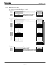
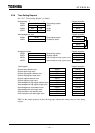
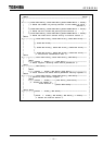
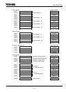
Input data area
Register allocation
0000H D02100
0001H Node address = 1 D02101
0002H D02102
0003H D02103
0004H Node address = 6 D02104
0005H D02105
0006H Node address = 8 D02106
0007H D02107
0008H Node address = 20 D02108
0009H D02109
000AH Node address = 22 D02110
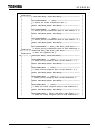
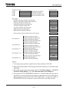
Output data area
Register allocation
0080H D1710
0081H
Node address = 1
D1711
0082H D1712
0083H
Node address = 6
D1713
0084H D1714
0085H
Node address = 20
D1715
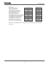
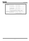
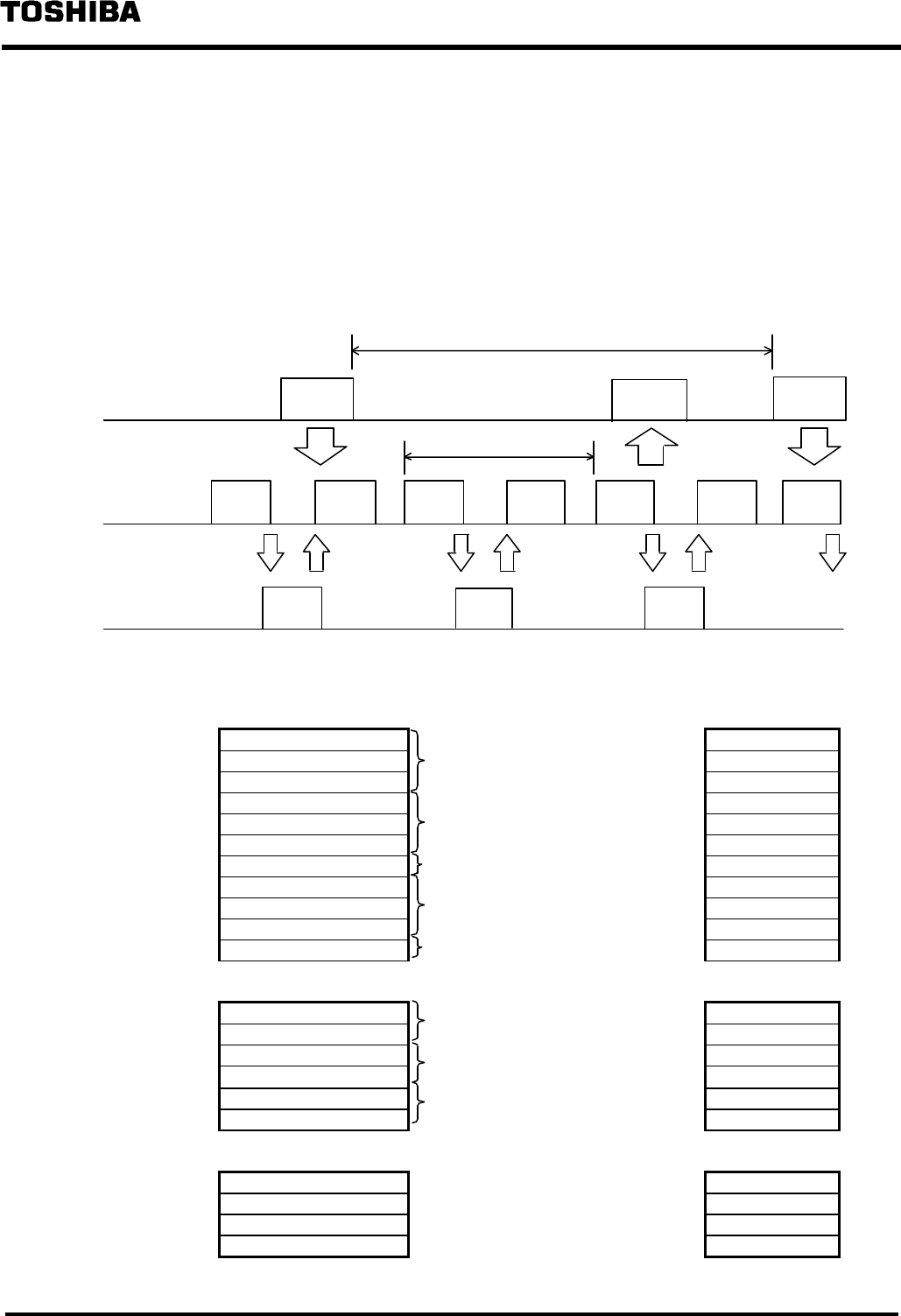
Bit strobe output data area
Register allocation
0100H D1700
0101H D1701
0102H D1702
0103H D1703