


6 F 3 B 0 3 6 4
38
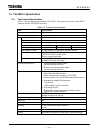
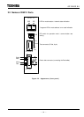
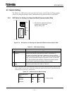
2.3 Functions of DN211 Parts
(1) LED for module status/network status indication (MS/NS)
This LED can light green/red. By making a distinction between green and red and lighting and
blinking, the DN211's module status (MS) and network status (NS) are indicated.
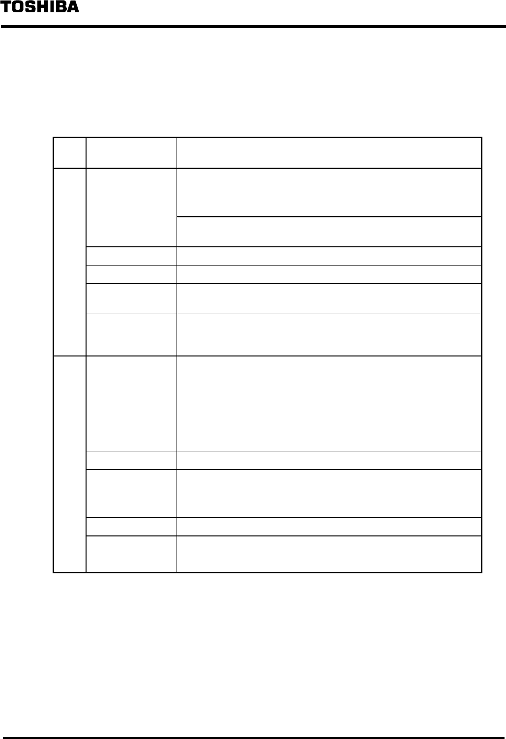
LED Indication
status
Meaning of the indication (main trouble)
MS Not lit • No power is supplied to the DN211.
• Though the power is supplied to the DN211, the module doesn't
become run mode (∗ 1).
When the 7-segment LED for node address/error code indicates the
local station node address, the power is supplied.
Green lighting • The DN211 is operating normally.
Green blinking • The DN211 is reading switch settings.
Red blinking • The DN211 is encountering a recoverable trouble.
→ Switch setting abnormal (DIP switch/rotary switch), etc.
Red lighting • The DN211 is encountering a non-recoverable trouble (down
status).
You may need to replace the module.
NS Not lit • No power is supplied to the DN211 (check MS).
• Though the power is supplied to the DN211, the module doesn't
become run mode ( ∗ 1); check MS.
• The DN211 is encountering a non-recoverable trouble (down
status); check MS.
• No network power is supplied to the DN211.
Green lighting • The DN211 is normally communicating with slave devices.
Green blinking • No communication between the DN211 and slave devices is
established.
• No slave devices are registered in the DN211.
Red blinking • No communication is established with more than one slave devices.
Red lighting • The DN211 communication is stopped due to busoff (∗ 2).
• Communication is stopped due to the node address duplicated.
(* 1) See "4.6 Requests to the DN211" for the run mode.
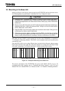
(* 2) Busoff: Individual nodes on the DeviceNet check for abnormal transmission paths; when the local
node is judged to be the cause of the abnormal transmission path, the local node is separated from
the transmission path. This state is called busoff.