


6 F 3 B 0 3 6 4
66
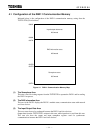
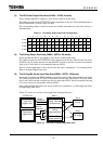
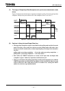
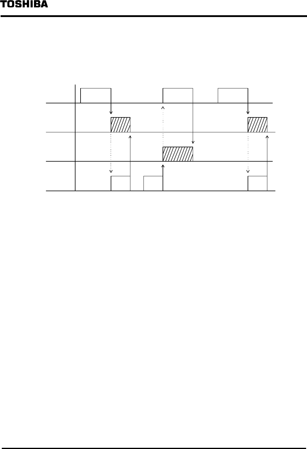
(7) The usage of Output/Input Data Semaphore (for synchronous transmission mode
alone)
Figure 4.4 indicates the relation between output data semaphore (polling / bit strobe) and input data
semaphore. Oblique lines parts indicate each of the semaphore values is set to the "1".
Output
processing
Intput
processing
Output
processing
T2/T2E/
T2N
Writes
output
comple-
tion "0"
Writes output
completion
"0"
Writes read
completion
"0"
Writes
output
instruction
"1"
Writes output
instruction "1"
DN211
Intput data
semaphore
Output data
semaphore
Writes in output
data area
Reads from
input data area
Writes in output
data area
Figure 4.4 Use of Semaphores in Synchronous Mode
(8) Cautions in Using the Input/Output Data Area
• The input data semaphore register is used both for the polling mode and the bit strobe
mode. Therefore, when some slave devices use the polling mode while other slave
devices use the bit strobe mode, set data input/output processing in the alternative
way like :
polling mode processing completion
→
bit strobe mode processing completion
→
polling mode processing completion
→
bit strobe mode
→ …
• Don't allow the WRITE instruction to execute in the input data area/input data
semaphore register. Otherwise, input data could be destroyed.
• When you write data in the polling output data area/bit strobe output data area with the
WRITE instruction, be careful of the top address of the area and the data size to be
written. Otherwise, data could destroy those in another area, causing the DN211
and/or slave devices to get malfunctioned.