


6 F 3 B 0 3 6 4
130
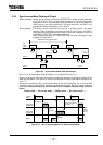
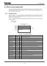
6.1 Module Status / Network Status LED (MS/NS)
The 2-color light-emitting diode (LED) on the front panel of the DN211 (module status/network
status LED) has two colors (green/red) to light, and blinking/not lit states, which distinctively
indicates the module status (MS) and the network status (NS).
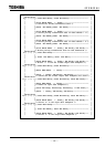
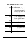
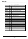
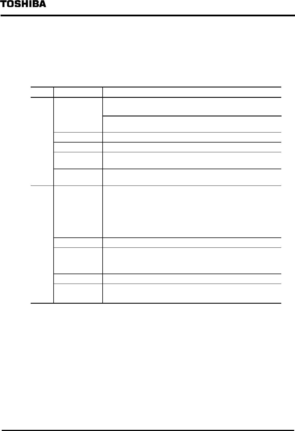
Table 6.1 Module Status / Network Status LED
LED Indication state Meaning of indication (major trouble)
MS • No power is supplied to the DN211.
• Although the power is supplied to the DN211, it is not in run mode.
Not lit
While the 7-segment LED node address/error code is indicating the
local station node address, the power is supplied.
Green lighting • The DN211 is normally operating.
Green blinking • The DN211 is reading switch settings.
Red blinking • The DN211 is encountering a recoverable trouble.
→ Switch setting abnormal (DIP switch / rotary switch), etc.
Red lighting • The DN211 is encountering an unrecoverable trouble (down state).
Yoy may have to replace the module.
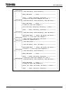
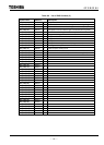
NS Not lit •No power is supplied to the DN211 (check MS).
• Although the power is supplied to the DN211, it is not in run mode
(check MS).
• The DN211 is encountering an unrecoverable trouble (down state:
check MS).
• No network power is supplied to the DN211.
Green lighting • The DN211 is normally communicating with slave devices.
Green blinking • No communication is established between the DN211 and slave
devices.
• Not a single slave device is registered in the DN211.
Red blinking • The DN211 is unable to communicate with an abnormal slave device.
Red lighting • Communication halted due to busoff in the DN211.
• Communication halted due to an overlapped node address.