


6 F 3 B 0 3 6 4
124
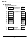
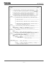
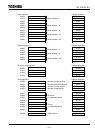
RAS information Register allocation
029BH Number of polling devices D1666
029CH Number of bit strobe devices D1667
029DH Number of online devices D1668
029EH Number of total devices D1669
0293H D1670
0294H Bit strobe D1671
0295H No-response device D1672
0296H D1673
0297H D1674
0298H Polling D1675
0299H No-response device D1676
029AH D1677
02CEH Station status D1665
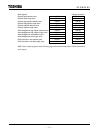
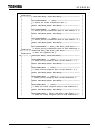
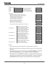
Work register Register allocation
RAS information read address store RW116
RAS information read data length store RW117
Request mode store of operation mode control request D1690
Polling input data top address D2502
Node address = 1 Number of polling input data words D2503
Polling output data top address D2504
Number of polling output data words D2505
Polling input data top address D2538
Node address = 6 Number of polling input data words D2539
Polling output data top address D2540
Number of polling output data words D2541
BS input data top address D2548
Node address = 8
Number of BS input data words D2549
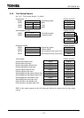
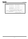
Polling input data top address D2622
Number of polling input data words D2623
Node address = 20
Polling output data top address D2624
Number of polling output data words D2625
BS input data top address D2632
Node address = 22
Number of BS input data words D2633
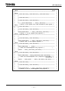
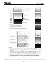
Remarks:
• This sample program performs loopback check of data transmitted to FLEX I/O.
• R0071 in the sample program on the next page indicates the startup relay for asynchronous data
input/output.
• This sample program requires the programs stated in "5.2.3 Reset Request", "5.2.4/5.2.5
Parameter Setting Request", and "5.2.6 Operation Mode Control Request."
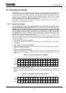
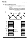
• This program allows the WRITE / READ instructions to write/read output and input data for
individual slave devices. Besides these performances, input/output data can be read/written in
batch processing (maximum 128 words). This method allows to reduce the number of
READ/WRITE executions, resulting in a shorter execution time for the ladder program.