


6 F 3 B 0 3 6 4
122
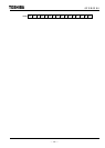
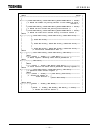
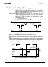
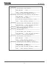
5.3.3 Synchronous Mode Data Input/Output
When outputting: Output data to slave devices from the T2/T2E/T2N is written into the output data
area of the DN211. Then, an output data semaphore or bit strobe output data
semaphore is used for commanding a polling instruction or bit strobe instruction.
When receiving the polling instruction / bit strobe instruction, the DN211 will
transmit the written output data to slave devices.
When inputting: The DN211 receives data from slave devices in polling response / bit strobe
response. When Completing receiving data from all slave devices, the DN211
will update data in the input data area. Then, an input data semaphore is used for
notifyingthe T2/T2E/T2N of the input completion.
When reading input data, the T2/T2E/T2N read data after checking for input
completion by the DN211.
Output
data
Input
data
Output
data
Output
processing
Intput
processing
Output
processing
Response Response
Intput
processing
T2/T2E/T2N Data Update Cycle
DN211
Slave
Input
completion
Input
completion
Output
instruction
Output
instruction
T2/
TE2/
T2N
Figure 5.5 Synchronous Mode Data Input/Output
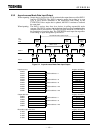
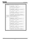
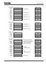
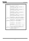
How to Use an Output/Input Data Semaphore (for synchronous mode only):
Figure 5.6 illustrates the relation between the output data semaphore (polling/bit strobe) and the
input data semaphore. The squares in oblique lines indicate the value of individual semaphores are
set to "1."
When devices with the polling system and bit strobe system are intermingled, use of the input data
semaphore register is shared by the polling mode and bit strobe mode. Therefore, input/output data
must be processed alternatively after the other mode completes the processing, as shown
below:
Polling mode
→
Bit strobe mode
→
Polling mode
→
Bit strobe mode
→ …
Writes
input
completion
"1"
Writes
output
completion
"0"
Writes in output
data area
Writes in output
data area
Output
processing
Intput
processing
Output
processing
T2/T2E/
T2N
Writes
output
comple-
tion "0"
Writes read
completion
"0"
Writes
output
instruction
"1"
Writes output
instruction "1"
DN211
Intput data
semaphore
Output data
semaphore
Reads from
input data area
Figure 5.6 How to Use Semaphores in Synchronous Mode