


6 F 3 B 0 3 6 4
39
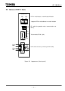
(2) 7-Segment LED for Node Address/Error Code Indication (NA/ERROR)
While the DN211 is normally transmitting data with slave devices the local station node address is
displayed.
Node address: A node identification number that the DeviceNet devices (nodes) linked to the
network have. The values range within 0 to 63 in decimal scale. In a DeviceNet, the
node address of a node linked to the network must be unique.
In the following cases, module or network status is displayed in combination of this LED and the
LED for module status/network status indication.
• A trouble occur on the DN211 or on the network.
• An error occurs when the T2/T2E/T2N requests.
(Parameter setting and operation mode controlling, etc. are performed by the request from the
T2/T2E/T2N.)
• The DN211 is downed.
See "6.2 Indications of the 7-Segment LED" for the combinations and meanings of this LED and
the LED for module status/network status indication.
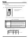
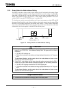
(3) DIP switch for setting the operation mode/communication rate
This DIP switch is used for setting the operation mode at DN211 busoff and a communication rate
on the network (500 kbps/250 kbps, 125 kbps).
"3.2 Switch Setting" explains the contents of the DIP switch and how to set it.
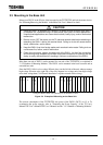
(4) Rotary switch for node address setting (NA-H/NA-L)
Is used for setting node addresses in the network of the DeviceNet.
The DN211 can have a node address within 0 to 63 (decimal scale) unless the node address doesn't
duplicate with another node address (slave device) in the network.
"3.2 Switch Setting" explains how to set the rotary switch.
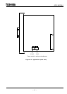
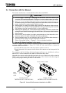
(5) The test connector
This connector is only for maintenance. You may not use it.
(6) The device side connector (for DeviceNet connection)
This connector is for connecting the DeviceNet cable to the DN211.
"3.4 Connection with the Network" explains how to connect cables.