6 F 3 B 0 3 6 4
30
1.4.3 Synchronization/Asynchronous Mode and Data Update Cycle
As explained in the preceding section, the communication function between the DN211 and slave
devices has the polling instruction/response mode and the bit strobe instruction/response mode.
Data can be exchanged between the T2/T2E/T2N and the DN211 in synchronous mode or
asynchronous mode. This section describes the synchronous mode/asynchronous mode.
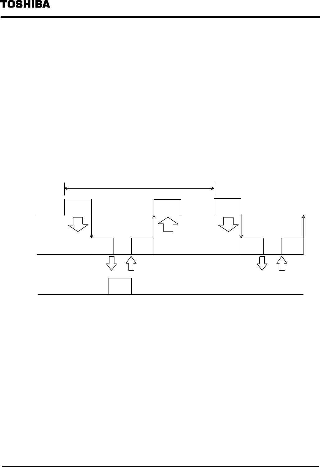
(1) The synchronous mode
At output: The T2/T2E/T2N writes output data to slave devices into the DN211 beforehand, and
activates a polling instruction/bit strobe instruction. When the polling instruction/bit
strobe instruction is activated, the DN211 sends the output data to slave devices.
At input: The DN211 receives data from slave devices by a polling response/bit strobe response.
After having received data from all slave devices, the DN211 arranges input data
before notifying the input completion to the T2/T2E/T2N. If the T2/T2E/T2N is reading
input data, it will check for the input completion by the DN211 before reading the input
data.
Output
data
Input
data
Output
data
Output
processing
Iutput
processing
Output
processing
Response Response
Intput
processing
T2/T2E/T2N Data Update Cycle
DN211
Slave
Input
completion
Input
completion
Output
instruction
Output
instruction
T2/
TE2/
T2N
Output data and input data exchanged between the T2/T2E/T2N ⇔ the DN211 are
synchronizing with the output/input cycles of the T2/T2E/T2N side program. For this reason, the
size of synchronous data value is equal to one-time output/input data to all slave devices.


