


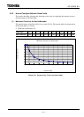
6 F 3 B 0 3 6 4
44
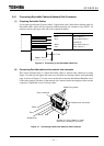
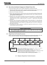
3.4.1 Connecting DeviceNet Cables to Network Side Connector
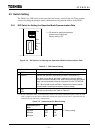
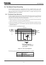
(1) Preparing DeviceNet Cables
Use an open-type cable end (2 power cables, 2 signal cables, and 1 drain cable in discrete state) for
DeviceNet cables, which will be connected with the network side connector of the DN211. Or
purchase such an open-type cable end in the commercial market.
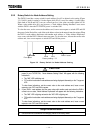
∼∼∼∼∼∼∼∼∼∼∼∼∼∼∼∼∼∼∼∼
Approx. 30 mm
5 to 7 mm
Figure 3.6 Processing of the DeviceNet Cable End
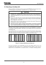
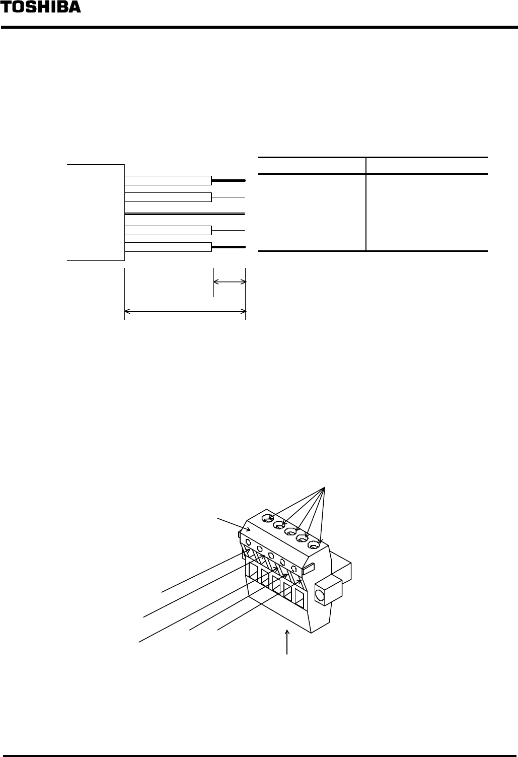
(2) Connecting DevicNet cables to the network side connector
This section describes how to connect DeviceNet cables to network side connectors by using
Figure 3.5 at the left side (upper and lower rows with holes for inserting cables) on the preceding
page. As shown in Figure 3.7, loosen screws on the cable connectors beforehand. Match the colors
of the cable coatings with those of the network side connector before inserting the cables into the
connectors. Tighten the screws for fixing cables.
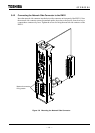
Figure 3.7 Connecting Cables with Network Side Connector
Color of cable coating Description
Black Power cable (V −)
Blue Signal cable (CAN_L)
− Shield/Drain
White Signal cable (CAN_H)
Red Power cable (V +)
Black
Color indication
Screws for fixing cables in lower-
row holes is located on this side
Shield/Drain
White
Red
Blue
Network side connector
Cable fixing screw