


6 F 3 B 0 3 6 4
36
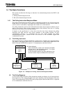
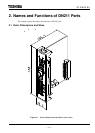
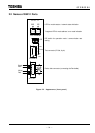
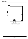
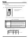
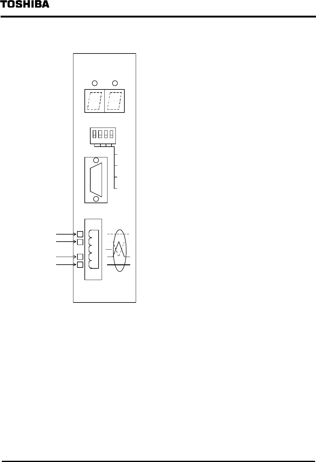
2.2 Names of DN211 Parts
1 2 3 4
DeviceNet
Figure 2.2 Appearance (front panel)
Red
White
Blue
Black
Device side connector (connecting the DeviceNet)
DIP switch for operation mode / communication rate
setting
7-segment LED for node address / error code indication
LED for module status / network status indication
Test connector (D-Sub, 9-pin)
LOADER
1
OSEN
2
BUSOFF
3
DR1
4
DR0
ON
NA / ERROR
D N 2 1 1
MS NS