


78-8130-6150-0 Rev G 15
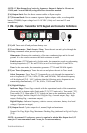
[13] Fault Finding Direction Indicators: Corresponds to the Earth Contact Frame
(A-Frame) probe (leg) colors.
[l4] External Jack: Port to connect cables from external devices such as the earth frame
(A-Frame), a second 3M
™
Dyna-Coupler, or a toning coil.
[15] Serial Port: RS232 port to connect the receiver to a PC via serial cable or USB-to-
serial adapter cable.
[16] Earphone Jack: Will fit standard 1/8" (3.175 mm) mini-jack mono earphone plug
(not included).
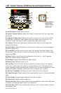
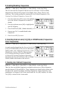
4. Menu Displays
A. Main Menu
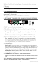
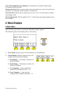
When the Menu [6] button is pressed, the Main Menu display appears.
The function appears on the display above each soft key.
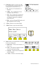
1. Write Mode: System used to write information to 3M iD Markers
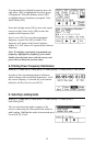
2. Data/Template: Displays marker history and
template creation/selection displays:
a. Read History – 100 memory locations for
Read iD Markers
b. Write History – 100 memory locations for
Written iD Markers
c. User Templates – Create and edit iD
templates for iD Markers (max = 32)
d. Trace Templates – Create and edit
templates used to identify path (max = 5)