


78-8130-6150-0 Rev G 23
B. Dyna-Coupler Method
! WARNING
This WARNING applies to the following 3M
™
Dyna-Couplers;
• 3" (75 mm) - Part number 3001
• 4.5" (114 mm) - Part number 4001
• 6" (150 mm) - Part number 1196
• All accessory kits containing any of the listed 3M Dyna-Couplers - Part numbers 3019, 4519,
1196/C
A potential for electrical shock exists when using the 3M Dyna-Coupler on cables energized
with electrical power. Use appropriate safety procedures.
DO NOT USE ON CABLES CARRYING IN EXCESS OF 600 VOLTS RMS.
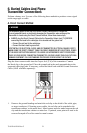
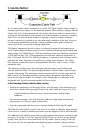
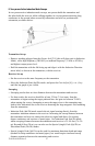
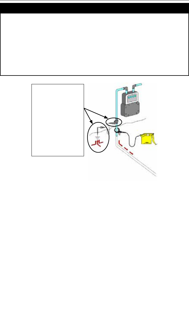
Use a ground extension cable,
or wire, and ground rod set-up
between a target pipe/cable and
a gas meter valve/box, or cable/
electrical meter box. This will
isolate the locate signal to the
target pipe/cable section below
the meter/box, between the
grounding points. This provides a
good return path for the tracing
signal. Insulating coupling above
a gas meter valve on a pipe will
isolate the returning signal from
ground and may make locating
more difcult.
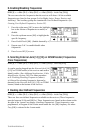
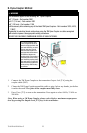
1. Connect the 3M Dyna-Coupler to the transmitter Output Jack [T-6] using the
coupler cable (9011).
2. Clamp the 3M Dyna-Coupler around the cable or pipe, below any bonds, just before
it enters the earth. The jaws of the coupler must fully close.
3. Press Trace [T-3] to turn on the transmitter. Press again to select 8 kHz, 33 kHz or
200 kHz.
Note: When using a 3M Dyna-Coupler, always select high or maximum output power
level by pressing the Output Level [T-5] key on the transmitter.