


38 78-8130-6150-0 Rev G
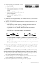
7. Continue along the cable path, re-inserting the 3M
™
Earth Contact Frame probes
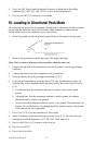
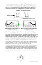
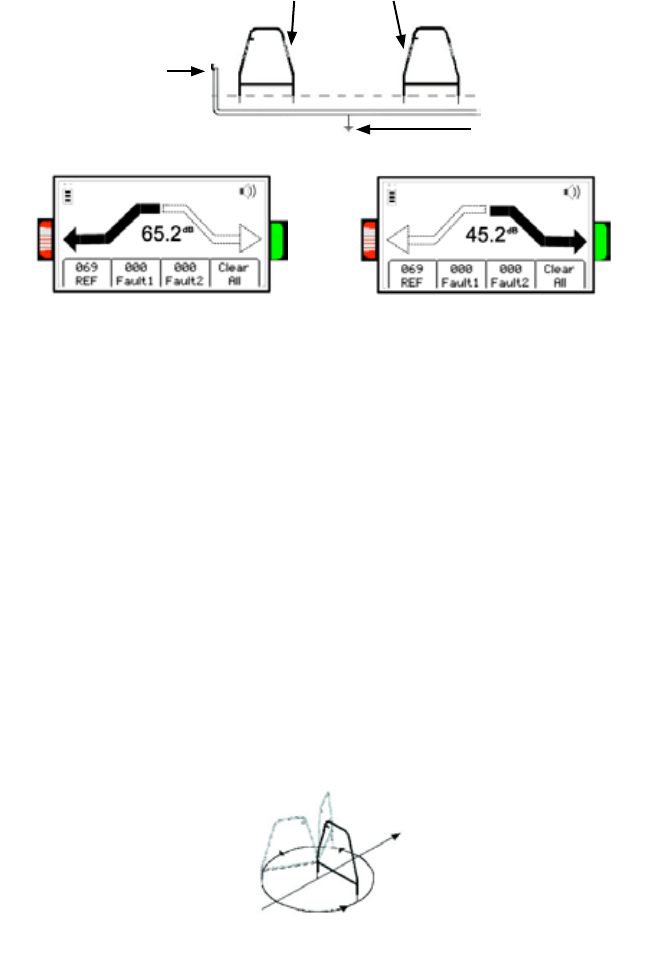
every few steps while watching the receiver bar graph. The bar graph on the
receiver will fill toward the right side of the display (green Fault Finding Direction
Indicator [13] (See illustration below)), indicating that the fault is ahead of the
operator (in the direction of the green-banded leg of the Earth Contact Frame).
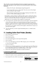
Transmitter Signal
Ground Fault location
Green Band Red-and-White-Striped Band
Move in direction of red-banded leg of
3M
™
Earth Contact Frame.
Move in direction of green-banded leg of
3M
™
Earth Contact Frame.
8. When the bar graph fills toward the left (red-and-white-striped Fault Finding
Direction Indicator [13] (See illustration above)) side of the display, the fault has
been passed and is now behind the operator. Move back, inserting the Earth Contact
Frame every few inches, until the arrows alternate back to green. Mark the point
beneath the center of the frame. Turn the Earth Contact Frame 90 degrees and insert
into the ground over the previously marked point. Move the Earth Contact Frame
to the left and right (following the directions of the green and red indicator arrows).
When the arrows reverse a third time, turn the Earth Contact Frame 90 degrees
again. Pinpoint the fault by moving the Earth Contact Frame in the direction of the
green and red arrows. The fault is located beneath the center of the Earth Contact
Frame when the arrows change from one side to the other this time.
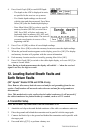
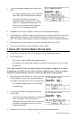
9. To verify the fault location, insert the Earth Contact Frame’s red-and-white-striped
probe directly on the spot identified above. Pivot the Earth Contact Frame in a
circle around the red-and-white-striped leg re-inserting the green-banded leg in the
ground every few degrees of the circle (Figure 2). The arrow should always point
toward the left (red) indicating that the fault is directly below the red-and-white-
striped leg.