


24 78-8130-6150-0 Rev G
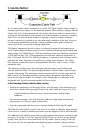
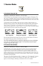
C. Induction Method
If you cannot make a direct connection, or use the 3M
™
Dyna-Coupler clamp to apply a
locating signal on the target, use the induction method. When nothing is plugged into the
Output Jack [T-6] of the transmitter the unit will be placed into induction mode when it
is turned on. This method uses the internal coil of the transmitter to generate a magnetic
field. This is the least preferred method of applying a signal on a target conductor
because it can easily be picked up by other non-target conductors in the area. However,
it is the preferred method of applying a signal to multiple cables/pipes in the same
trench, and for the ‘two-person sweeping’ application.
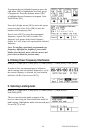
3M Dynatel transmitters provide a choice of induction frequencies and output power
levels. Higher induction output power levels are needed for detecting deeper depths and
longer ranges. The 2200M Series 3 Watt transmitters provides two induction frequencies:
33 kHz and 200 kHz. The 12 Watt transmitter provides three induction frequencies: 8
kHz, 33 kHz and 200 kHz. The 200 kHz frequency is commonly used for deeper cables/
pipes and the lower frequencies are used to give longer locate distances. The 8 kHz
(low frequency) induction helps in locating shallow facilities, such as risers (12 Watt
transmitter only.)
The following sections review Non-sweeping and Sweeping (Area) methods used
with the Induction Mode. The Non-Sweeping method is utilized when a specific target
requires path tracing. The transmitter remains stationary in-line over the target and the
path is traced. The Sweeping method is utilized when a designated area needs to be
swept for non-specific targets, for example, all the buried pipes or conductors in the
designated area. Several sweeping methods will be reviewed.
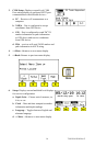
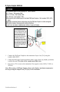
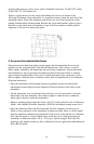
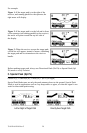
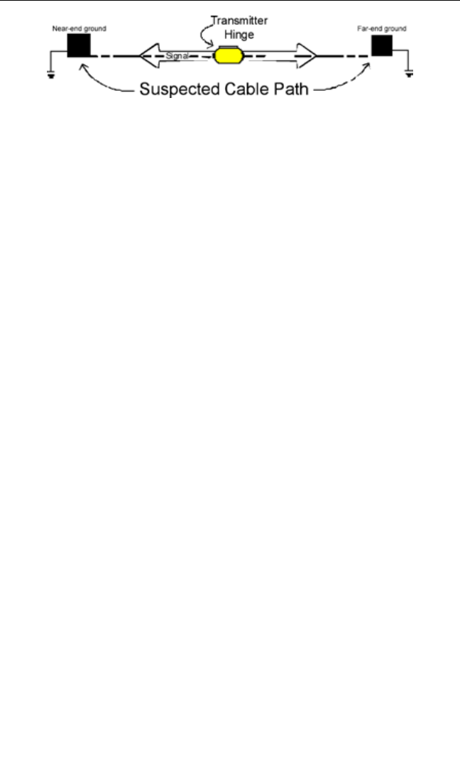
A. Non-Sweeping (Passive) Induction Mode Locating
• Position the transmitter over the target facility, with the hinge of the transmitter over
and in line with the cable/pipe path. Remove any cables from the Output Jack [T-6].
− Align the Induction Direction arrows on the transmitter with the target
conductor.
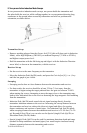
• Turn on the transmitter, select the frequency and select high output or maximum
output power level for best signal-to-noise ratio.
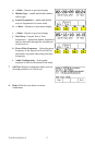
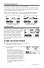
• Trace the signal path with the receiver using the Induction Peak (Ind Pk) mode.
The Induction Peak (Ind Pk) mode of the receiver is a mode in which the upper antenna
of the receiver is tuned to minimize distortion from the magnetic field of the transmitter.
Use Induction Peak (Ind Pk) mode when sweeping distance between the transmitter and
receiver is 25–60 feet (7.6–20 m). Beyond 60 feet (20 m) you can also use the Special
(single) Peak (Spl Pk) or Directional Peak (Dir Pk) modes. Special (single) Peak (Spl
Pk) can be used for maximum detection depth and range (needed for deep conductors