


78-8130-6150-0 Rev G 55
19. Additional Applications
A. Aerial Faults (Toning)
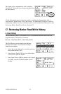
1. Transmitter Setup
1. Connect the transmitter (based on type of fault) as described in Connection
Diagrams in the following section.
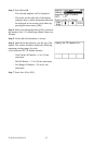
2. Press and hold off [T-1] to perform a battery test.
3. Press on: Ohm-meter/Fault Locate/Tone [T-2] to turn the Transmitter on and to
verify the fault.
4. Press on: Ohm-meter/Fault Locate/Tone [T-2] twice more to select the Tone mode.
5. The Digital Display [T-4] will alternately flash between 577 and 200K.
6. Press Output Level [T-5] for high or maximum output level.
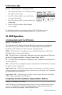
2. Receiver Setup
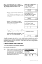
1. Press On/Off (Power) [T-1] to turn the receiver on.
2. Press Locate/OK [5]
3. Press Tone/Ext [SK] to select Tone mode.
4. Press Freq [SK Toggle] to select 577Hz.
5. Connect a toning coil to the receiver External Jack [14] ([13] on 2250M
transmitter).
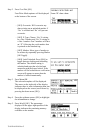
6. Move the toning coil along the cable and find a peak signal, then press Gain [4]
down to adjust the receiver gain.
7. Press Speaker Volume Control (Spkr/Xpnd) [2] to adjust the speaker volume as
needed.
8. Follow the cable with the toning coil.
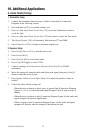
− When the receiver detects a short, cross, or ground fault (Connection Diagram
Figures #1, #2, or #3), the audio and Signal Strength [10] will stop or drop off
sharply.
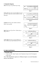
− When the receiver detects a split (Connection Diagram Figure #4) the audio and
signal strength will increase significantly.
− When verifying a split (Connection Diagram Figure #5) the audio and signal
strength will decrease after the toning coil has passed the split.