


78-8130-6150-0 Rev G 21
6. Buried Cables And Pipes:
TransmitterConnections
Perform a battery test. Use one of the following three methods to produce a trace signal
on the target pipe or cable.
A. Direct Connect Method
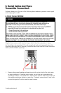
! WARNING
This WARNING applies to the use of the Direct Connect Cables and the Transmitter.
To avoid potential shock, or electrically damaging the Transmitter, when setting up the
Transmitter to locate using the Direct Connect method, follow these basic steps;
• ALWAYS plug the Direct Connect Cable into the Transmitter Output Jack [T-6] BEFORE
connecting the leads to the cable/pipe to be located and the ground rod.
– Connect the red lead to the cable/pipe.
– Connect the black lead to ground rod.
A POTENTIAL FOR ELECTRICAL SHOCK, AND/OR TRANSMITTER ELECTRICAL DAMAGE, EXISTS
WHEN USING THE DIRECT CONNECT CABLE ON CABLES ENERGIZED WITH ELECTRICAL POWER
IF THE ABOVE INSTRUCTIONS ARE NOT FOLLOWED. USE APPROPRIATE SAFETY PROCEDURES.
CHECK VOLTAGE BEFORE CONNECTING TRANSMITTER. VOLTAGE HIGHER THAN 240 VOLTS WILL
DAMAGE EQUIPMENT. FOLLOW STANDARD PROCEDURES FOR REDUCING THE VOLTAGE.
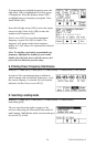
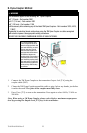
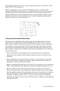
Plug the direct connect cable into the Output Jack [T-6] of the transmitter. Connect
the black clip to the ground rod. Place the ground rod in the earth perpendicular to the
suspected cable/pipe path. If necessary, extend the black lead with the Ground Extension
Cable (#9043 available separately).
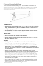
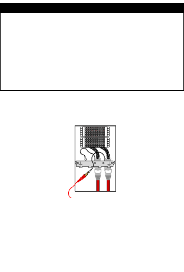
1. Remove the ground bonding and attach the red clip to the shield of the cable, pipe,
or target conductor. (If locating power cables, the red clip can be attached to the
transformer cabinet, or the meter box). Metal contact must be made between the red
clip and the transformer cabinet or meter box. If painted, some paint will need to be
removed/scraped off to allow metal-to-metal contact.