


144 Chapter 4
ESA Functional Tests
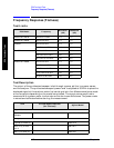
Frequency Response (Flatness)
ESA Functional Tests
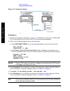
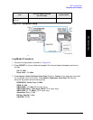
2. Connect the equipment as shown in Figure 4-3.
CAUTION Use only 75 Ω cables, connectors, or adapters on analyzers with 75 Ω
connectors, or damage to the connectors will occur.
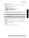
3. Set the synthesized sweeper controls as follows:
FREQUENCY, Center Freq, 50, MHz
POWER LEVEL
, –8, dBm
4. Press System, Power On/Preset, Preset Type (Factory), Preset on the analyzer and wait for
the preset routine to finish. Set the analyzer by pressing the following keys.
FREQUENCY, 50, MHz
CF Step
, 50, MHz
SPAN
, 20, kHz
AMPLITUDE
, More, Y Axis Units, dBm
AMPLITUDE
, –10, dBm
AMPLITUDE
, Attenuation, 10, dB
Scale/Div
, 2, dB
BW/Avg
, Res BW, 10, kHz
Video BW
, 3, kHz
Peak Search
FREQUENCY
, Signal Track (On)
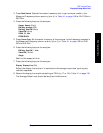
5. Adjust the synthesized sweeper power level for a marker amplitude reading of –14 dBm
+/– 0.10 dB.
NOTE The power level of the synthesized sweeper remains unchanged for the
duration of the test. For each new test frequency, the power sensor cal factor
should be entered to minimize measurement errors.
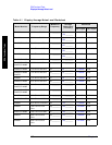
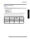
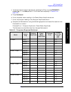
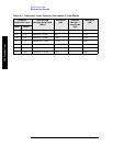
6. Refer to Table 4-3 on page 145 Enter the marker readout amplitude for 50 MHz as
displayed on the analyzer in the Analyzer Amplitude column.
7. Enter the power meter reading in the Power Meter Amplitude column.
8. Compute the flatness error at 50 MHz using the following equation and record the
results in the Flatness Error column:
Flatness Error = Analyzer Amplitude – Power Meter Amplitude
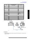
9. Perform the following steps for each center frequency setting listed in Table 4-3 on
page 145.
a. Tune the source to the next frequency listed in the Center Frequency column.
b. Enter the power sensor cal factor for the new test frequency.