


164 Chapter 4
ESA Functional Tests
Tracking Generator Level Flatness: E4402B, E4403B, E4404B, E4405B, E4407B and E4408B,
Option 1DN
ESA Functional Tests
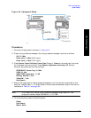
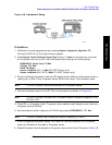
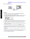
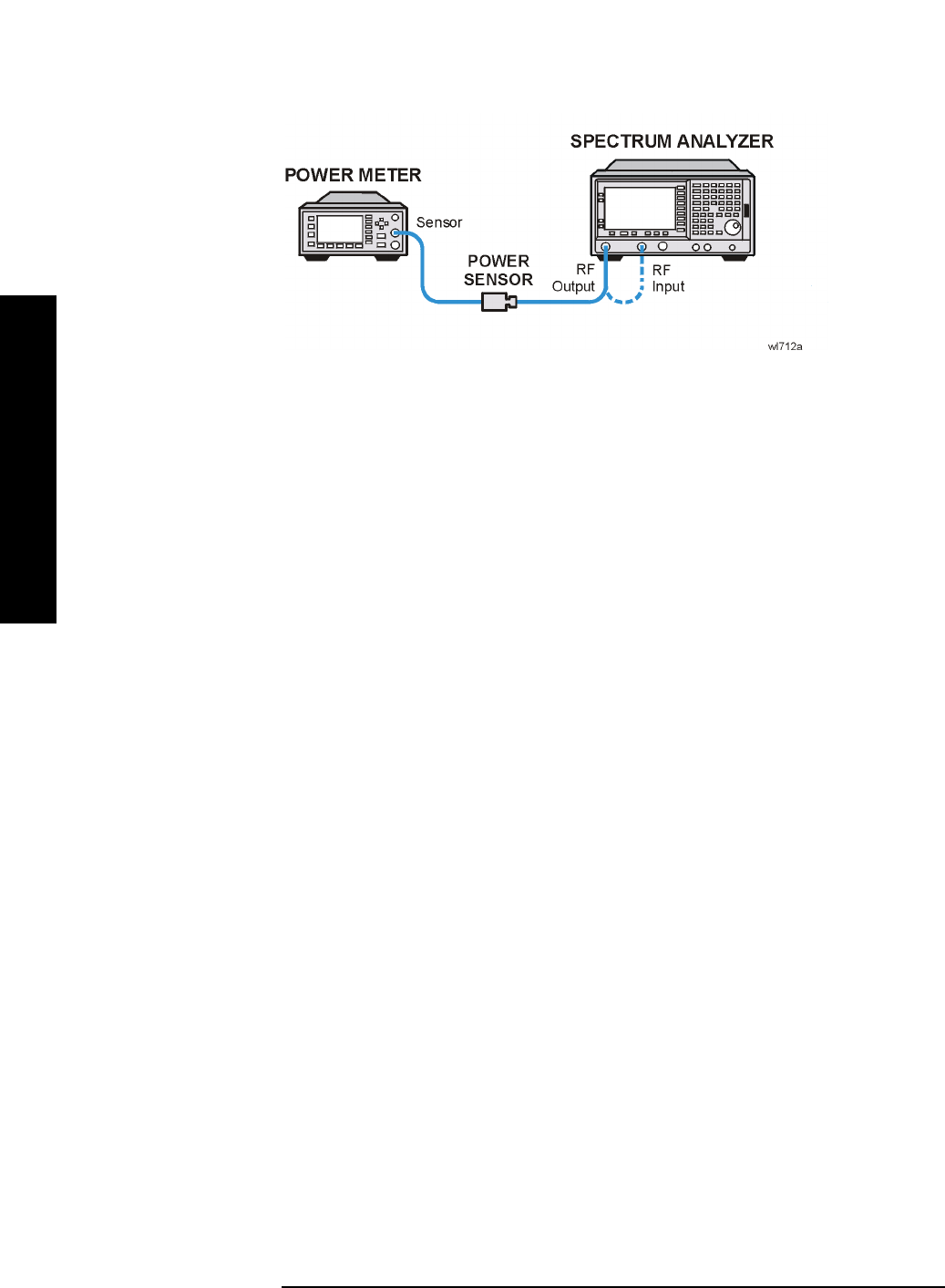
Figure 4-9 Equipment Setup
Procedure
1. Calibrate the tracking generator by pressing System, Alignments, Align Now, TG.
Connect the RF OUT to the RF INPUT when prompted.
2. Press
System, Power On/Preset, Preset Type (Factory), Preset on the analyzer, then wait
for the preset routine to finish. Set the analyzer by pressing the following keys:
FREQUENCY, Center Freq, 50, MHz
CF Step
, 100, MHz
SPAN
, Zero Span
Source,
Amplitude (On), –20, dBm
System
, Alignments, Auto Align, Off
3. Zero and calibrate the power meter and power sensor. Make sure the power meter is
reading out in dBm. Enter the power sensor 50 MHz cal factor into the power meter.
4. Connect the power sensor to the RF Out on the analyzer as shown in Figure 4-9.
5. Press REL on the power meter. The power meter readout amplitudes are now relative to
the power level at 50 MHz.
6. Set the analyzer center frequency to 100 kHz by pressing
FREQUENCY, 100, kHz.
7. Enter the appropriate power sensor Cal Factor for the test frequency into the power
meter as indicated on the label of the power sensor. This must be done at each test
frequency.
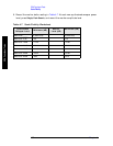
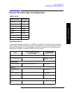
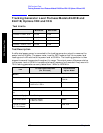
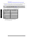
8. Record the power level displayed on the power meter as the Level Flatness in Table 4-9
on page 165.
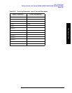
9. Repeat steps 5 through 7 to measure the flatness at each center frequency setting listed
in Table 4-9. The
⇑ may be used to tune to center frequencies above 500 MHz.
10.Press
System, Alignments, Auto Align, On.