22-4
Cisco IOS Software Configuration Guide for Cisco Aironet Access Points
OL-29225-01
Chapter 22 Troubleshooting
Checking the Top Panel Indicators
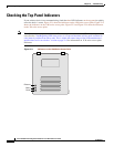
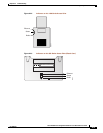
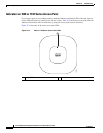
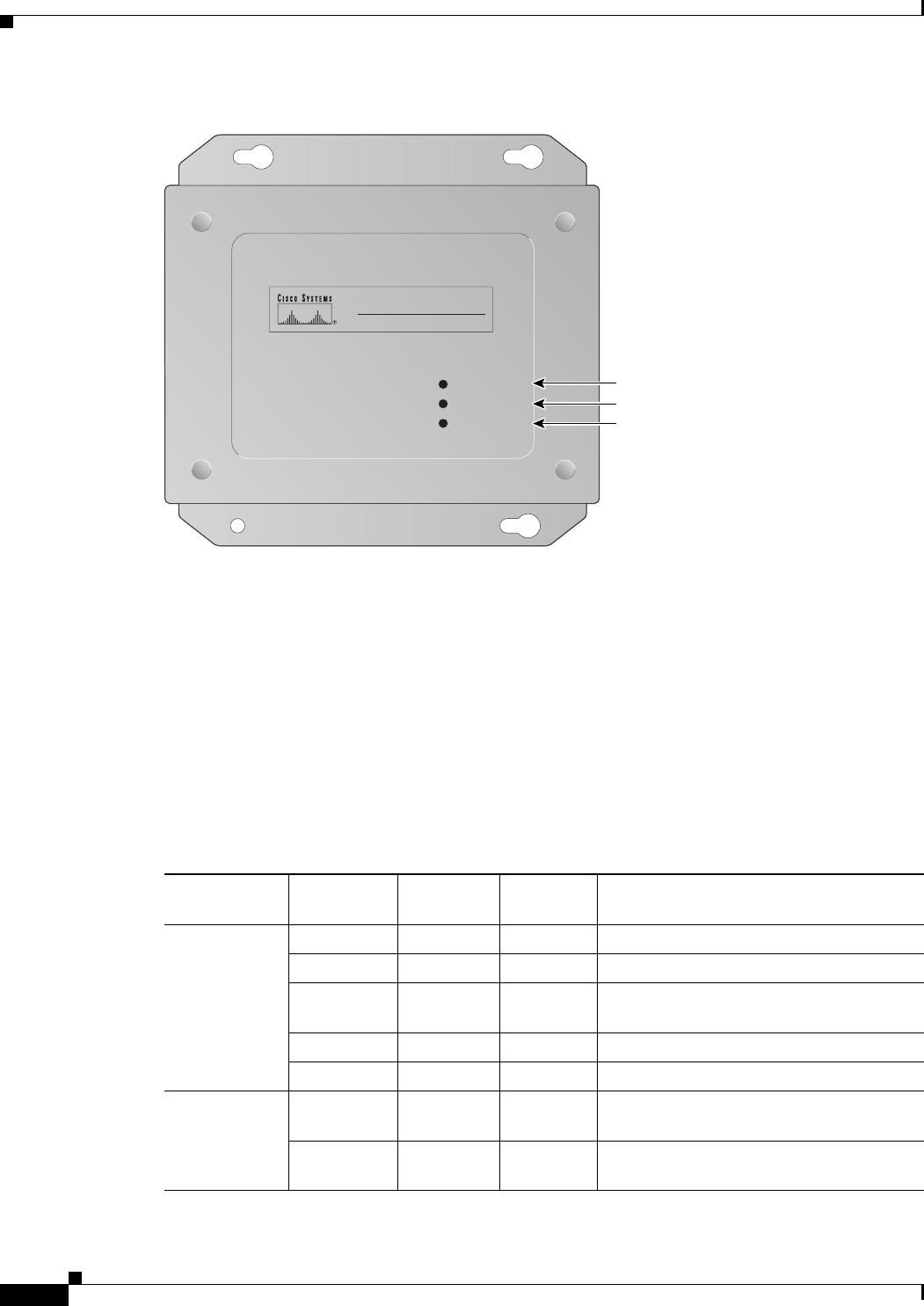
Figure 22-4 Indicators on the 350 Series Access Point (Metal Case)
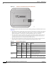
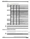
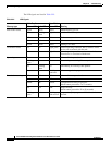
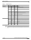
The indicator signals on the wireless device have the following meanings (for additional details refer to
Table 22-1):
• The Ethernet indicator signals traffic on the wired LAN. This indicator is normally green when an
Ethernet cable is connected, and blinks green when a packet is received or transmitted over the
Ethernet infrastructure. The indicator is off when the Ethernet cable is not connected.
• The status indicator signals operational status. Steady green indicates that the wireless device is
associated with at least one wireless client. Blinking green indicates that the wireless device is
operating normally but is not associated with any wireless devices.
• The radio indicator blinks green to indicate radio traffic activity. The light is normally off, but it
blinks whenever a packet is received or transmitted over the wireless device’s radio.
60511
CISCO AIRONET 350 SERIES
WIRELESS ACCESS POINT
ETHERNET ACTIVITY
ASSOCIATION STATUS
RADIO ACTIVITY
Ethernet
Status
Radio
Ta b l e 22- 1 Top Panel Indicator Signals
Message
type
Ethernet
indicator
Status
indicator
Radio
indicator
Meaning
Boot loader
status
Green – Green DRAM memory test.
– Amber Red Board initialization test.
– Blinking
green
Blinking
green
Flash memory test.
Amber Green – Ethernet initialization test.
Green Green Green Starting Cisco IOS software.
Association
status
– Green – At least one wireless client device is
associated with the unit.
– Blinking
green
– No client devices are associated; check the
wireless device’s SSID and WEP settings.


