


22-11
Cisco IOS Software Configuration Guide for Cisco Aironet Access Points
OL-29225-01
Chapter 22 Troubleshooting
Checking the Top Panel Indicators
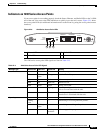
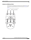
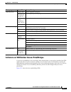
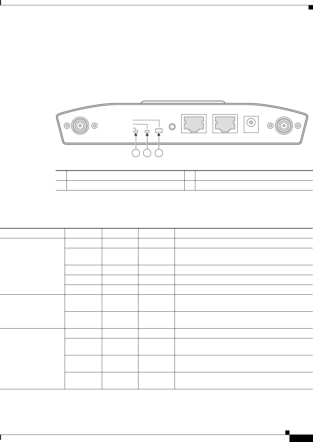
Indicators on 1240 Series Access Points
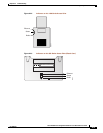
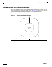
If your access point is not working properly, check the Status, Ethernet, and Radio LEDs on the 2.4 GHz
end of the unit. You can use the LED indications to quickly assess the unit’s status. Figure 22-1 shows
the access point LEDs (for additional information refer to the Event Log using the access point browser
interface).
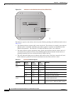
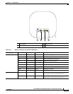
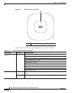
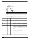
Figure 22-6 1240 Series Access Point LEDs
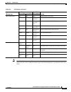
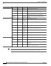
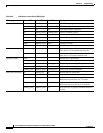
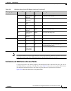
The 1240 series access point LED signals are listed in Table 22-5.
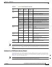
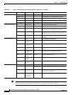
Table 22-4 1240 Series Access Point LED Signals
1 Ethernet LED 3 Radio LED
2 Radio LED
STATUS
RADIO
ETHERNET
MODE
CONSOLE
ETHERNET
48VDC
2.4 GHz RIGHT/PRIMARY
2.4 GHz LEFT
135497
321
Message type Ethernet LED Radio LED Status LED Meaning
Boot loader status Green Green Green DRAM memory test ok.
Off Blinking
green
Blue-green Initialize Flash file system.
Off Green Pink Flash memory test ok.
Green Off Dark blue Ethernet test ok.
Green Green Green Starting Cisco IOS.
Association status — — Light green Normal operating condition, but no wireless client
devices are associated with the unit.
— — Blue Normal operating condition, at least one wireless
client device is associated with the unit.
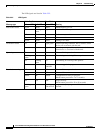
Operating status Green — — Ethernet link is operational.
Blinking
green
— — Transmitting or receiving Ethernet packets.
—Blinking
green
— Transmitting or receiving radio packets.
— — Blinking
dark blue
Software upgrade in progress