


Chapter 2. Hardware Description
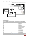
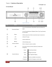
3. Rear Port Specification and Connection Examples
Page 31
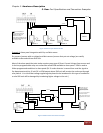
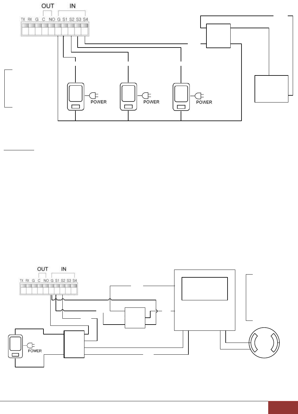
Sensor 1
+5V DC
Sensor 2
Sensor 3
+5V DC +5V DC
+5V DC
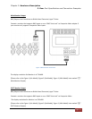
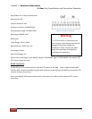
Sensors are outputting no
voltage, however DVR unit
requires 5 volt DC to get
response for sensor.
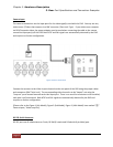
Some Device outputting 12V DC
should have Relay that provides
dry contact to DVR.
V
+
V
out
C
+
GND
C
-
Relay Switch
+12V DC
Device
Figure 18 Sensor input with 3 volt DC
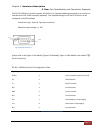
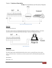
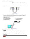
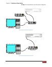
Example 3. Alarm panel integration with Dry and Wet sensor.
Dry sensors (sensors with no voltage) and Wet sensors (sensors that put out voltage) are readily
available to be used with our DVR unit.
Most of the alarm panel that exist today requires some type of Direct Current Voltage from sensors and
it also has programmable relay-out connection called PGM available to alarm panel. PGM is used to
follow programmed conditions in alarm panel (EX: if smoke detector is sensed then send the signal to
fire department and trip 12 volt DC to PGM output where DVR unit will receive the such event through
relay switch. It is critical that voltage regulating relay board to be introduced in this type of installation
or else DVR unit will be damaged by introducing higher voltage to the unit.)
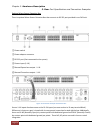
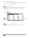
Sensor 2
Programmable output from
Alarm panel call PGM will
provide ground output and it
receives 12V DC from Alarm
Panel
Sensor 1 port is used in DVR for
Arm and Disarm Function.
So PGM1 of Alarm panel should
be programmed for Arm and Dis-
Arm
V
+
V
out
C
+
GND
C
-
Relay Switch
Smoke Detector
C
B
Alarm Panel
V
in1
V
in2
V
out1
V
out1
V
out2
V
out2
Relay Switch
+5V DC
+3V DC
PGM1
+12V DC
+5V DC
Figure 19 Alarm Panel and Sensor Example