


0150-0193F 12 Kalatel DVMRe Triplex
Pin 1: Alarm Input 1.
Pin 2: Alarm Input 2.
Pin 3: Alarm Input 3.
Pin 4: Alarm Input 4.
Pin 5: Alarm Input 5.
Pin 6: Alarm Input 6.
Pin 7: Alarm Input 7.
Pin 8: Alarm Input 8.
Pin 9: Alarm Input 9.
Pin 10: Alarm Input 10.
Pin 11: Alarm Input 11.
Pin 12: Alarm Input 12.
Pin 13: Alarm Input 13.
Pin 14: Alarm Input 14.
Pin 15: Alarm Input 15.
Pin 16: Alarm Input 16.
Pin 17: Alarm Output Relay #1.
Pin 18: Ground.
Pin 19: Ground.
Pin 20: Ground.
Pin 21: Alarm Output Relay #1 Common.
Pin 22: Alarm Output Relay #2.
Pin 23: External Alarm Silence and Acknowledge Input.
Pin 25: Alarm Output Relay #2 Common.
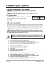
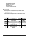
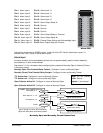
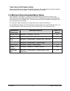
NO1A1 A2A14 A15 A16A3 A4 A5 GND
A
7
GNDA6
NO2 COM1
G
N
D
A8A9A10 GNDACKA11VextA12A13 COM2
171 214 15 163 4 5 18 7196
Signal
PIN
22 21 208910 202311241213 25
Signal
PIN
Alarm PCB
Active alarm inputs vary by DVMRe model. 4 channel units (4CT) have 4 active alarm inputs. 10
channel units (10CT) have 10 active alarm inputs.
Alarm Input
An alarm condition can be activated by devices such as pressure pads, passive infrared detectors,
door switches, or other similar devices.
See section 3.11 for information about configuring the contacts as Normally Open or Normally Closed
in the menu system.
Normally Open, Zero Potential Relay Contact: Configure in menu as Normally Open.
Normally Closed, Zero Potential Relay Contact: Configure in menu as Normally Closed
TTL Active High: Configure in menu as Normally Closed.
TTL Active Low: Configure in menu as Normally Open.
Open Collector Active On: Configure in menu as Normally Open.
High: 5V (12V Tolerant)
Low: Ground
Inputs: 1 per channel.
Open Collector Active Off: Configure in menu as Normally Closed.
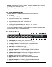
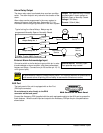
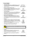
pin 16
pins 18
-
20
Alarm Input No. 2 - 15
pins 2-15
Alarm Input No. 1
Normally Closed
(Opens During Alarm)
DVMRe Triplex DB25 Connector
Typical Alarm Device
Normally Open
(Closes During Alarm)
Typical Alarm Device
pin 1
Alarm Input No. 16
Ground
Typical wiring for Alarm #1 as Normally
Open and Alarm #16 as Normally Closed.
Refer to each alarm device's manual for specific wiring details.
Normally Open and Normally Closed Connections