


Chapter 2 - Installation
RF300E/RF310E 13
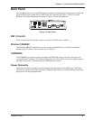
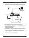
Cabling Your RASFinder
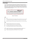
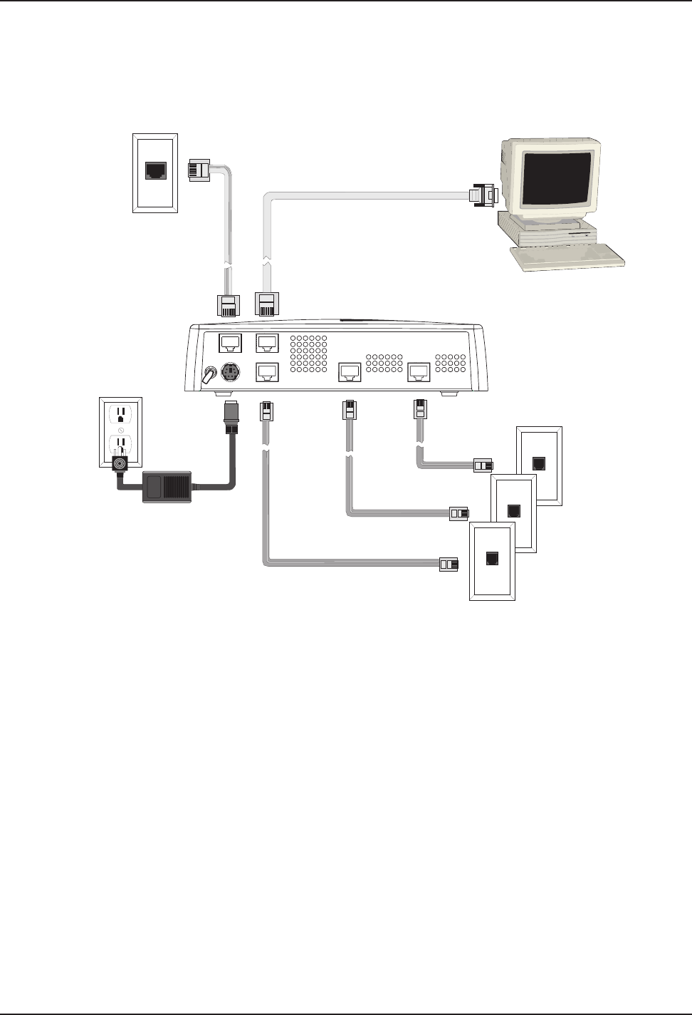
Cabling your RASFinder involves making the proper WAN, Ethernet, Command Port, and Power
connections. Figure 2-2 shows the back panel connectors and the associated cable connections.
The procedures for connecting the cables to your RASFinder are provided below.
Power Connection
Ethernet Connection
COMMAND
10BASET
POWER
0
1
BRI 3 BRI 2 BRI 1
WAN Connections
Figure 2-2. Back Panel Connections
Note: If additional RAM is needed, perform the procedure in the next section, Adding Additional RAM.
The following steps detail the procedures for connecting the cables to your RASFinder.
1 Connect the RASFinder to a PC using the short RJ-45 to DB9 (female) cable provided with the unit.
Plug the RJ-45 end of the Command cable into the Command Port of the RASFinder and the other
end into the PC's serial port. See Figure 2-2.
2 Connect an RJ-45 (UTP) cable to the 10 BASE-T connector on the back of the RASFinder. Connect
the other end of the cable to your LAN.
3 Connect one end of a UTP cable to each of the BRI Connectors on the RASFinder (labeled BRI 1,
BRI 2, and BRI 3) and connect the other end to a WAN jack (as shown in Figure 2-2).
4 Connect one end of the power supply to a live AC outlet, then connect the other end to the
RASFinder as shown in Figure 2-2. The power connector is a 6-pin circular DIN connector.
5 Turn on power to the RASFinder by setting the ON/OFF switch on the back panel to the ON position.
At this time your RASFinder is completely cabled.
Proceed to the next section to install the RASFinder software.