Chapter 1 - Introduction and Description
RF300E/RF310E 9
Back Panel
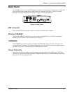
All the cable connections for the RASFinder are made at the back panel. Three groups of cables (all
using RJ-45 jacks) are used with the RASFinder: the Command Port, BRI 1 (2 and 3), and the
Ethernet. The cable connections are shown in Figure 1-3 then defined below.
COMMAND
10BASET
POWER
0
1
BRI 3 BRI 2 BRI 1
Figure 1-3. Back Panel
BRI 1 (2 and 3)
Each of these three RJ-45 jacks is used to connect the RASFinder to a WAN.
Ethernet 10BASET
The Ethernet 10BASET connector is used to connect the RASFinder to a LAN over unshielded
twisted pair (UTP) cable. This connector is an RJ-45 jack.
COMMAND
The COMMAND connector is used to configure the RASFinder using a PC with a serial port and
running Windows
®
software. The Command connector is an RJ-45 jack, and a short adapter cable is
provided to convert to a standard serial port DB9 female connector.
Power Connector
The Power connector is used to connect the external power supply to the RASFinder. The Power
connector is a 6-pin circular DIN connector. A separate power cord is connected between the power
supply and a live AC grounded outlet.


