


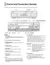
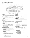

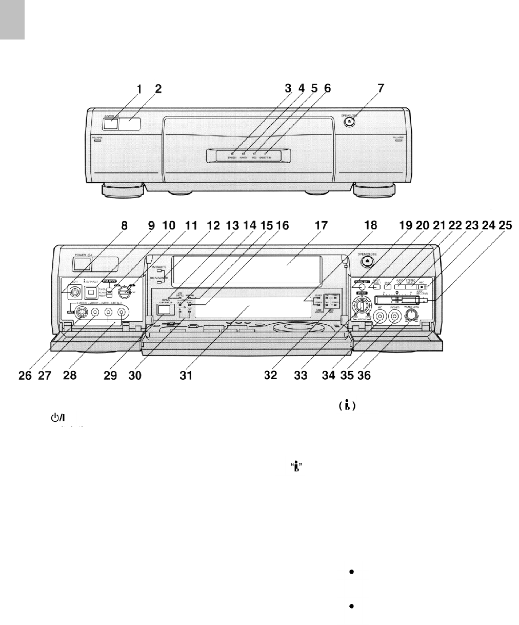
Control and Connection Sockets
This section gives a detailed explanation of the function of each button, switch and connection socket.
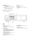
FRONT
1
2
3
4
5
6
7
8
POWER
Press to switch the VCR from on to standby mode or
vice versa. In standby mode, the unit is still connected to
the mains.
Infra-red Remote Control Receiver Window
STANDBY Indicator
This indicator is lit when main lead is connected and the
power is off.
POWER Indicator
This indicator is lit when the power is on.
REC Indicator
This indicator is lit when recording is in progress.
CASSETTE IN Indicator
This indicator is lit when a cassette is inserted.
OPEN/CLOSE
Press to open the front panel or to open/close the
cassette tray.
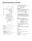
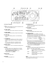
EDIT
By connecting a movie camera or VCR with an EDIT
socket to this socket via an Edit cable, various kinds of
editing functions can be performed more quickly and
efficiently between two VCRs or between a VCR and a
movie camera.
9 DV IN/OUT
To connect the DV cable to digital video equipment with
IEEE 1394-1995 compatible DV terminal.
"i.LINK” is the name of the connector in accordance with
the International Standard IEEE1394-1995.
is the logo marked on products conforming with the
“i.LINK” specifications. For further details on the DV
terminal, refer to the Glossary of Terms on page 66.
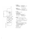
10 EDIT MODE
PLAYER:
When this VCR is used as the playback
VCR during editing operations.
RECORDER:
When this VCR is used as the recording
VCR during editing operations.
Normally set at this position.
PASSIVE:
When operating this VCR using another
VCR or an editing controller.
The picture quality best suited for
editing is selected.
11 EDIT CONTROL
To select a connected component when another
component is to be connected for editing, etc.
12 DV CASSETTE/MINI CASSETTE Indicators
This indicator corresponds to the size of the cassette
inserted is lit.
4