


– 76 –
Setup menus
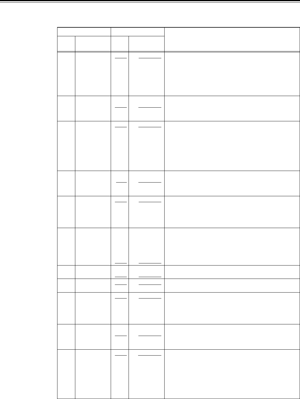
USER menu
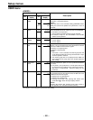
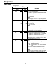
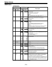
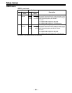
<INTERFACE>
Item Setting
No.
Superimposed
No.
Superimposed
Description
display display
200 PARA RUN 0000 DIS
0001 ENA
201 9P SEL 0000 OFF
0001 ON
202 ID SEL 0000 OTHER
0001 DVCPRO
0002 ORIG
203 50P SEL 0000 OFF
0001 ON
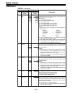
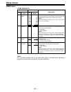
204 RS232C SEL 0000 OFF
0001 ON
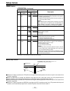
205 BAUD RATE 0000 300
0001 600
0002 1200
0003 2400
0004 4800
0005 9600
206 DATA 0000 7
LENGTH 0001 8
207 STOP BIT 0000 1
0001 2
208 PARITY 0000 NON
0001 ODD
0002 EVEN
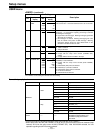
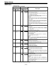
209 RETURN 0000 OFF
ACK 0001 ON
210 50P STBY 0000 OFF/ON
CMD 0001 ON
The underline on the setting item denotes the initial setting.
This selects whether two or more VTRs are to be operated in
synchronization.
0: No operation in synchronization
1: Operation in synchronization
<Note>
When operating two or more VTRs in synchronization, set all
the VTRs to 0001 (ENA). (See pages 9 and 17.)
This selects whether the 9P connector functions when the
REMOTE/LOCAL switch has been set to REMOTE.
0: Do not function
1: Function
This selects the ID information which is returned to the
controller.
0: 20 25H
1: The DVCPRO’s original ID (F0 33H) is returned.
2: The unit’s original ID (A0 50H) is returned.
<Note>
The 2(ORIG) setting should only be used when a Panasonic
controller (AJ-A900 etc, sold separately) is connected.
This selects whether the PARALLEL (50P) connector functions
when the REMOTE/LOCAL switch has been set to REMOTE.
0: Does not function
1: Functions
These settings are for selecting whether the RS-232C
connector is to function when the REMOTE/LOCAL switch is
set to REMOTE.
0: Connector does not function.
1: Connector functions.
These settings are for selecting the RS-232C communication
speed (baud rate).
These settings are for selecting the RS-232C data length.
(Unit: bit)
These settings are for selecting the RS-232C stop bit length.
(Unit: bit)
These settings are for selecting the none, odd or even for the
RS-232C parity bit.
0: Parity bit is not used.
1: An odd number of bits is used for the parity system.
2: An even number of bits is used for the parity system.
These settings are for selecting whether the ACK code is to be
returned when a command is received from RS-232C.
0: ACK code is not returned.
1: ACK code is returned.
For selecting the method used to detect the STANDBY
COMMAND signal input at the PARALLEL (50P) connector.
0: Each time active signals are detected, the STANDBY ON or
STANDBY OFF mode is selected alternately.
1: When active signals are detected in the STANDBY OFF
mode, the unit is transferred to the STANDBY ON mode.
Nothing happens if they are detected during an operation in
the STANDBY ON mode.