


13
RQTV0134
STEP 1 Connection
This section includes diagrams of two common methods of connection (A-B, pages 13-14). Please connect using the one that best
suits you.
≥Visit Panasonic’s homepage for more information about connection methods. (This is in English only.)
http://www.panasonic.com/consumer_electronics/dvd_recorder/dvd_connection.asp
≥Before doing any connection, turn off all the equipments and read the appropriate operating instructions.
≥Peripheral equipments and optional cables are sold separately unless otherwise indicated.
≥You need to subscribe to a cable TV or satellite service to enjoy viewing their programme.
≥Consult your service provider regarding appropriate cable box.
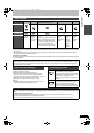
∫The unit’s RF OUT terminal
The picture and sound signal from this unit go through the RF OUT
terminal to the television.
Refer to page 14 if the antenna connector doesn’t match.
∫When the unit is not to be used for a long time
To save power, unplug it from the household AC outlet. This unit
consumes a small amount of power, even when it is turned off
(approx. 8 W
).
TV TV
The unit
VCR
VCR
The unit
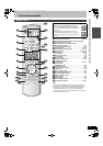
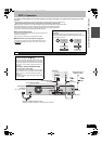
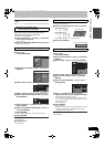
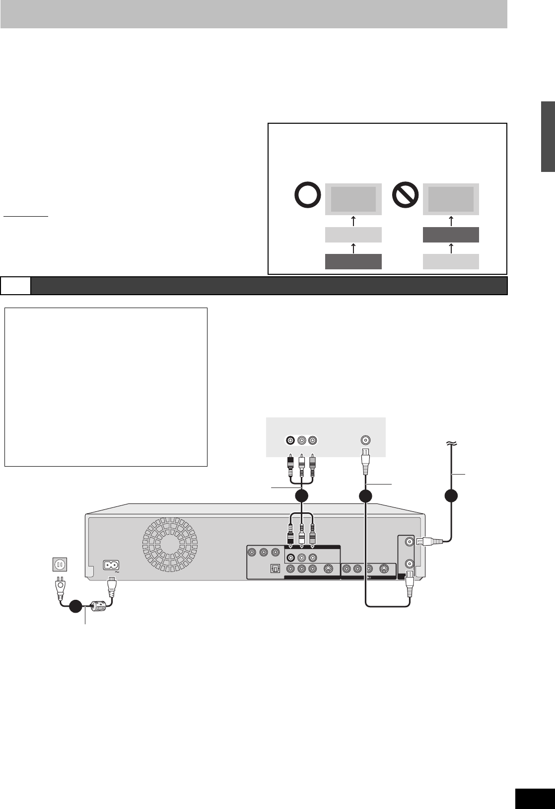
∫Do not connect the unit through a video cassette
recorder
Video signals sent through video cassette recorders will be
affected by copyright protection systems and the picture will not be
shown correctly on the TV.
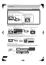
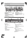
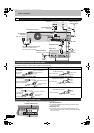
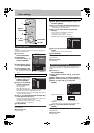
A Connection with a television
R-AUDIO-L
VIDEO
R-AUDIO-L
VIDEO
S VIDEO
Y
P
B
PR
OPTICAL
COMPONENT VIDEO OUT
DIGITAL AUDIO OUT
(PCM/BITSTREAM)
DVD/VHS COMMON OUT
RF
OUT
VHF/UHF
RF
IN
R-AUDIO-L
VIDEO
S VIDEO
AC IN
DVD PRIORITY OUT
VHF/UHF
RF IN
AUDIO IN
VIDEO
IN
RL
Red White
Red White
Yell
ell
owRed White Yellow
1
2
To RF IN
To
To
DVD/VHS COMMON OUT
DVD/VHS COMMON OUT
To
DVD/VHS COMMON OUT
Television
This unit’
s rear pane
l
Audio/Video cable
(Included)
To RF OUT
To household
AC outlet
(AC 120 V, 60 Hz)
AC power supply cord (Included)
Connect only after all other connections are complete.
75 h
h
coaxial
cable
(Included)
75
h
h
coaxial
cable
Cable from wall or
antenna signal
3
4
Red White
Red White
Yell
ell
owRed White Yellow
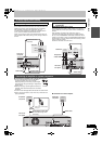
∫ Connection (with Audio/Video cable)
Connect in numerical order 1 to 4.
≥After this connection, set the RF output channel “OFF”
(l 16), and then press TV/VIDEO button of TV remote
controller to select the AV input mode to the connected
TV terminal. You can watch a video from this unit on
your TV.
∫Connection (without Audio/Video cable)
You do not need to connect “3”.
The unit supplies a signal to the TV via the 75 ≠ coaxial
cable on channel 3 or 4. It is possible to view the video
picture on your TV in the same way that you watch TV
broadcasts.
≥After this connection, set the RF output channel “CH3”
or “CH4” (l 16).
Control reference guide/STEP 1 Connection
M6VP&PC.book 13 ページ 2006年2月6日 月曜日 午後3時20分