


13
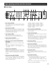
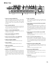
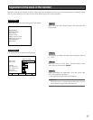
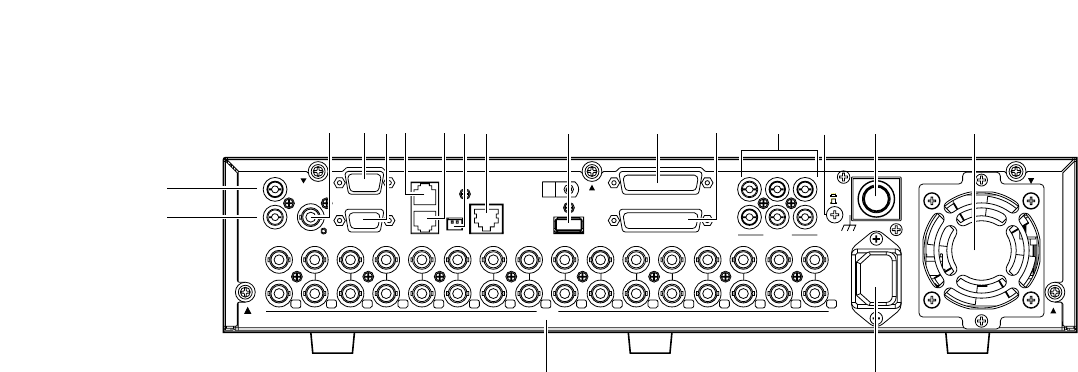
q Audio out connector (AUDIO OUT)
Audio will be output from this connector. Audio being
input to the AUDIO IN/ALARM OUT terminal or to the
AUDIO IN connectors will be output. When playing
recorded images, audio recorded with the images will
be output.
w Aux in connector (AUX IN)
Use for audio communication between the recorder and
the PC (remote talk). Audio from the microphone con-
nected to this connector will be input.
e Monitor 1 connector (BNC) (MONITOR1)
Images from the cameras connected to the VIDEO IN
connectors will be output.
r Serial terminal (D-SUB, 9-pin) (SERIAL)
This terminal is unavailable.
t Monitor 2 terminal (D-SUB, 15-pin) (MONITOR2)
Connect a video monitor to this connector.
y RS485 port (RS485 (CAMERA))
Connect an RS485 combination camera to this port.
u Data port (DATA)
Connect a PS·Data compatible device to this port.
i Mode switch (MODE)
Use to determine the operational mode of this recorder.
(☞ page 47)
o Network port (10/100BASE-T)
Connect a LAN cable between this port and the net-
work port of a PC. When the recorder is connected with
a network correctly, the link indicator beside the port
will light orange. When data flows through the network
port, the access indicator beside the port will blink
green.
!0 Copy 1 port (COPY1)
When an external recording device is connected to this
port, images recorded on the built-in HDD can be
copied onto it.
!1 Audio in/Alarm out terminal (D-SUB, 25-pin) (AUDIO
IN/ALARM OUT)
Connect an alarming device such as a buzzer or an
alarm lamp to this terminal. When a device such as a
microphone amplifier is connected, audio from it will be
input. Audio being input to this terminal will be output
from the AUDIO OUT connector of the unit and the con-
nected PC.
!2 Alarm in/Control terminal (D-SUB, 25-pin) (ALARM
IN/CONTROL)
Connect an alarming device such as a sensor or a door
switch to this terminal.
!3 Audio in connectors (RCA) (AUDIO IN, 1 - 6)
This connector is the line-in connector. Connect a
device such as a microphone amplifier to input audio
from it. Audio being input to this terminal will be output
from the AUDIO OUT connector of the unit and the con-
nected PC.
!4 Signal ground terminal (SIGNAL GND)
Connect a grounding wire between this terminal and
the signal ground terminal of the other device in the
system.
Otherwise, it may cause oscillation or noise.
!5 Power button (POWER ON/OFF)
When this button is pressed and the power is turned on,
the unit starts operation.
When this button is pressed again and the power is
turned off, operation stops.
!6 Cooling fan
When the temperature inside the unit becomes high,
this fan starts automatically.
AUX IN
AUDIO OUT
IN
OUT
16 15 14 13 12 11 10 9 8 7 6 5 4 3
531
642
12
14 13 12 11 10 9 8 7 6 5 4 3 2 116 15
MONITOR1 MONITOR2
RS485(CAMERA)
MODE
12
DATA
10/100BASE-T COPY1
ALARM IN/CONTOROL
AUDIO IN
SIGNAL GND
POWER
ON
OFF
AC IN
AUDIO IN/ALARM OUT
VIDEO
SERIAL
w
erty uio
!8
q
!7
!0 !1 !2 !3 !4 !5 !6
■ Rear View