


78
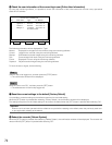
AUDIO IN connectors –10 dBv 51 kΩ, unbalanced, x16 (CH1 - 6: RCA, CH7 - 16,
D-SUB 25-pin)
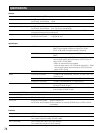
Audio
AUDIO OUT connector –10 dBv 1 kΩ, unbalanced, x 1 output (RCA)
External AUDIO IN connector –52dBv 2.2 kΩ, unbalanced, x1 input (RCA)
ALARM IN Non-voltage make contact, pulse width 100 ms or more,
x16 input (D-SUB, 25-pin)
Alarm
ALARM OUT Normally open/Normally closed/Common, 1A 30 V DC max.,
4 each output (D-SUB, 25-pin)
10BASE-T/100BASE-TX x1 (RJ-45)Network (10/100BASE-T) port
RS485 x1 (RJ-11)RS485 (CAMERA) port
RS485 x1 (RJ-11) (Currently unavailable)Data port (DATA)
WJ-RT416, WJ-RT416K: SERIAL interface x2
WJ-RT416V, WJ-RT416VK: SERIAL interface x2, internal CD/DVD drive x1 (CD-R, DVD-R
compatible)
COPY port
MPEG-4
NTSC model: Field (704 x 240), SIF (352 x 240)
PAL model: Field (704 x 288), SIF (352 x 288)
NTSC model: Max. 30 ips (for each channel)
PAL model: Max. 25 ips (for each channel)
Image compression method
Resolution
Rec. Frame Rate
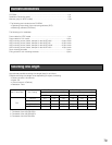
Weight WJ-RT416K, WJ-RT416VK: 11 kg {24.28 lbs.}
WJ-RT416, WJ-RT416V: 12 kg {26.49 lbs.}
General
Input/Output
Function
Specifications
Power source
Video
Power consumption
Ambient operating temperature
Ambient operating humidity
Dimensions
120 V AC, 60 Hz (NTSC model), 220 - 240 V AC, 50 Hz (PAL model)
VIDEO IN connectors Composite video input signal 1 V[P-P]/75 Ω, x16 input
(BNC) Control-signal multiplex x4 input (CH1–CH4)
*CH5 - CH8 (when an optional board is installed)
MONITOR1 connector Composite video output signal 1 V[P-P]/75 Ω, x1 output
(BNC)
MONITOR2 terminal RGB output x1 (D-SUB, 15-pin), 1024 x 768 resolution
5 °C - 45°C {41 °F - 113 °F}
WJ-RT416, WJ-RT416K: 110 W
WJ-RT416V, WJ-RT416VK: 120 W
WJ-RT416, WJ-RT416K: 5 % - 90 % (non condensing)
WJ-RT416V, WJ-RT416VK: 10 % - 80 % (non condensing)
430 mm (W) x 88 mm (H) x 459 mm (D) {16-15/16" (W) x 3-7/16" (H) x 18-1/16"(D)}
(excluding rubber feet and projections)
VIDEO OUT connectors Active-through output 1V[P-P]/75 Ω x4 output (CH1 - CH4)
Loop-through output (auto termination) 1V[P-P]/75 Ω x12
output (CH5 - CH16) (BNC)
* When an optional board is installed
Active-through output 1V[P-P]/75 Ω x8 output (CH1 - CH8)
Loop-through output (auto termination) 1V[P-P]/75 Ω x8
output (CH9 - CH16)