Operation
3-413160-A2-GB21-50 January 1997
Enabling the Communication
Port for Carrier-Mounted
DSU/CSUs
Communication between the carrier-mounted
DSU/CSUs and an external PC, ASCII device, SNMP
manager, or async terminal interface (attached either
locally or through an external modem) occurs through a
shared communication (COM) port. (For COM port
cabling information, refer to the COMSPHERE 3000
Series Carrier Installation Manual.) Unlike standalone
DSU/CSUs, the carrier-mounted DSU/CSUs do not have a
dedicated COM port for external access. Once the COM
port is enabled, other COM port configuration options can
be selected. These options are used to configure Port 2 on
the Auxiliary Backplane as a COM port for the carrier.
NOTE
If a Model 3161 DSU/CSU has
the COM port enabled, Port 2
cannot be used as a data port.
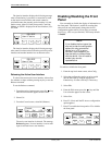
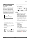
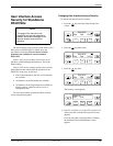
To enable the COM port on the carrier-mounted
DSU/CSU,
1. From the top-level menu screen, select Cnfig.
2. Select the configuration option set to be copied
into the Edit area by using the appropriate
Function key. Use the scroll keys, if necessary.
3. Select Edit.
4. From the Edit screen, press the
key until the
User selection appears on the screen.
5. Select User.
F1
Edit:
Chan Gen User
F2
F3
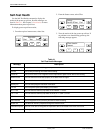
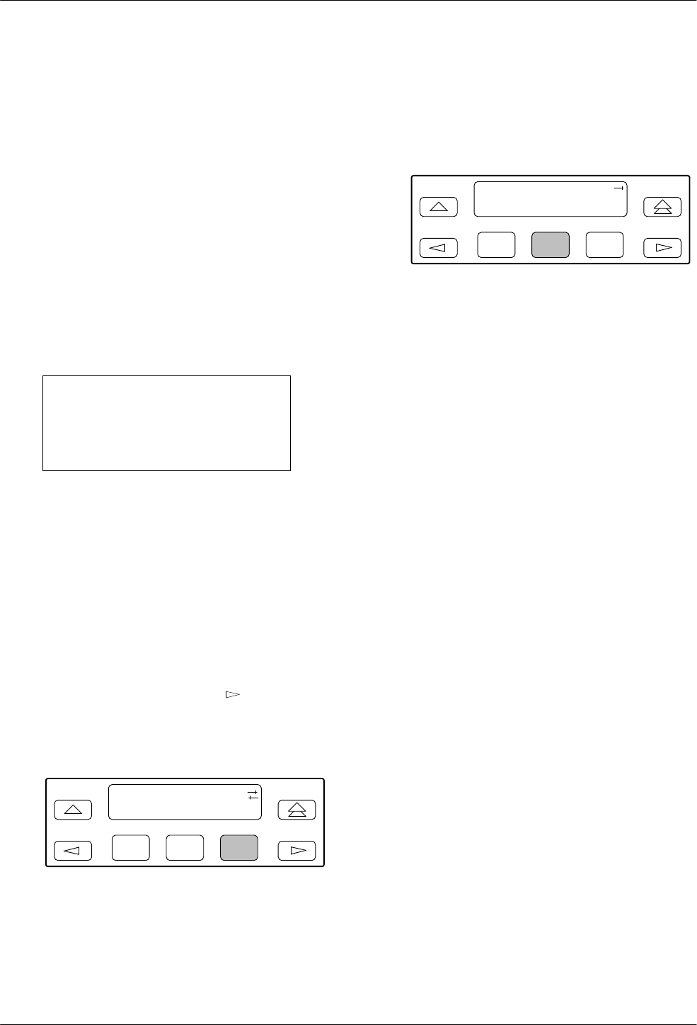
6. Press F1 (Next) until the Com Port configuration
option appears.
7. Select Enab to enable the COM port for the
carrier-mounted DSU/CSU.
F1
Com Port:
Next Enab Disab
F2
F3
The carrier COM port provides the following
functionality:
• If configured for ASCII, only one ASCII device
may be used for the carrier. (If two COM ports are
configured for ASCII, neither will work.)
• If configured for Mgmt, each device in the carrier
can support an Mgmt COM port; however, each
Mgmt COM port must be connected to a different
subnet. To facilitate IP data routing, the device with
the closest link to the SNMP manager or Telnet
client should be configured as the IP Bus Master.
• If configured for either ASCII or Mgmt, the carrier
COM port may be configured to control an external
device (e.g., modem, x.25 PAD) through the use of
AT or user-specified commands.
The set of valid characters for control of the carrier
external COM port device is as follows:
• The numbers: 0–9
• The lowercase letters: a–z
• The uppercase letters: A–Z
• The space (“ ”) character
• The ASCII symbols (in ascending order, based on
the ASCII code)
• The End Of Line (EOL) symbol: ←
• The caret (‘‘^”) control character is used to select
non-printable ASCII characters. The caret ‘‘^” must
be followed by one character which together form
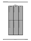
the control sequence. Table 3-7 defines all of the
available control sequences.


